Do you have a question about the AOX AOX-Q Series and is the answer not in the manual?
The shell is made of aluminum alloy with anodic oxidation and polyester powder coating, offering corrosion resistance and enclosure IP67.
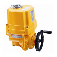
Features asynchronous motor, manual structure with handwheel, and self-locking worm gear mechanism for efficient torque transfer.
Includes a continuous position indicator, space heater for condensation prevention, and adjustable limit switches.
Details torque switch for overload protection, anti-off bolts, and circuit layout meeting power supply standards.
Covers valve position display on LCD, automatic phase sequence adjustment, and international installation standards.
Table detailing maximum output torque, operating time, shaft size, power, rated current for single and three phases, and handwheel revolution.
Specification table covering shell enclosure, power, motor type, limit switches, torque switch, travel, temperature, and materials.
Lists various optional schemes for actuators, including explosion-proof, water-proof, control units, and temperature resistance.
Provides visual representation and installation dimensions for AOX-Q models from 005 to 120.
Provides visual representation and installation dimensions for AOX-Q models from 150 to 600.
Wiring diagram for single-phase, on/off controlled AOX-Q models 005-010 with 110/220VAC power.
Wiring diagram for single-phase, on/off controlled AOX-Q models 015-600 with 110/220VAC power.
Wiring diagram for single-phase, modulating controlled AOX-Q models 005-010 with 110/220VAC power.
Wiring diagram for single-phase, standard modulating controlled AOX-Q models 015-600 with 110/220VAC power.
Wiring diagram for three-phase, external standard on/off controlled AOX-Q models 015-600 with 380/440VAC power.
Wiring diagram for single-phase, intelligent on/off controlled AOX-Q models 015-600 with 110/220VAC power.
Guidelines for selecting installation sites, considering interior/outdoor conditions, ambient temperature, and fluid temperature.
Step-by-step instructions for mounting the electric actuator onto the valve, ensuring correct alignment and connection.
Instructions for connecting power cables, using appropriate joints, and ensuring waterproof arrangements.
Procedure to adjust mechanical limit stoppers and locknuts for precise full-close and full-open positions.
Steps for setting travel limit cams to define the full-closed and full-open travel limits using micro switches.
Guidance on adjusting the potentiometer for feedback signals, ensuring correct resistance values for opening and closing movements.
Procedure for adjusting the over torque protection mechanism by setting limit switch cams.
Instructions for aligning the indicator plate and window glass for accurate valve position indication.
Details technical parameters and debugging procedures for Proportion Adjustable Control Units (PCU).
Procedure for performing manual operation of the actuator to check its movement before electrical testing.
Steps for checking wiring and initiating electric operation after manual verification.
| Series | AOX-Q Series |
|---|---|
| Category | Controller |
| Input Voltage | 24V DC |
| Communication Interface | Ethernet |
| Dimensions | Varies by model |
| Weight | Varies by model |