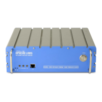
ANAN-200D Accessory Port [back panel]
The Hermes/Angelia schematic detail J16 pin numbering does not correspond to keyed IDC ribbon
cable numbering conventions. An IDC to DB25 adapter cable further re-arranges the pin numbers.
Pin out and connections between 26 pin J16, Modified [shifted] 26 pin IDC ribbon cable and DB 25.
J16 1 2 3 4 5 6 7 8 9 10 11 12 13 14 15 16 17 18 19 20 21 22 23 24 25 26
IDC 26 25 24 23 22 21 20 19 18 17 16 15 14 13 12 11 10 9 8 7 6 5 4 3 2 1
DB25 13 25 12 24 11 23 10 22 9 21 8 20 7 19 6 18 5 17 4 16 3 15 2 14 1
NOTE: Left channel line audio input is the "Line In" source on the Setup, transmit tab. This input
can be used instead of the mic jack. Pin 13 is PTT in.
NOTE: The speaker jack contains the Left Channel speaker pair. The Right Channel speaker pair is
on pin 6 and Pin 19. These are balanced outputs. Do NOT ground these lines!
The OpenHPSDR/PowerSDR Setup, ANAN Ctrl tab numbering scheme for the J16 Receive and
transmit pins does not represent the actual pin numbers.
ACC/IO Port pinout. name schematic pin numbers
1 Open-drain PTT output
25vdc @ 800ma
25
2 OC6 User open-collector output 7 23
3 OC4 User open-collector output 5 21
4 OC2 User open-collector output 3 19
5 OC0 User open-collector output 1 17
6 Right channel speaker Pair with pin 19 15
7 User Digital input 4: connected to 3.3V
via 1K pullup resistor
13
8 User Analog input 1: 0-3V max 11
9 User Digital input 1: Connected to
3.3V via 1K pullup resistor
9
10 Left channel line Out 7
11 Right channel phones output 5
12 Left channel line-level audio input* 3
Copyright Apache Labs © ANAN-200D 54 June 22, 2015