NOTE: After completing the Yoke Reassembly, go directly to the
section on ADJUSTING THE FIRST STAGE on pg 12.
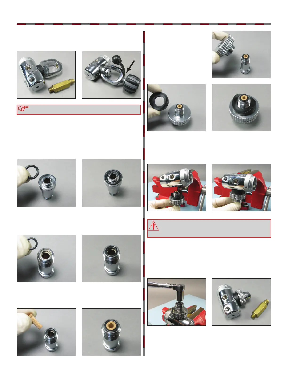
CAUTION: The handwheel connector must be held verti-
cally while being installed upwards into the body until snug.
Failure to do this can cause the o-ring not to seat properly
which in turn will create a high pressure leak.
DST First Stage Technical Maintenance Manual
11
7
Remove the rst stage from the bench vise and remove the vise
mounting tool. Attach the protective cap (28) to the yoke clamp
(27) by stretching it over the ange at the top of the yoke clamp.
Thread the yoke screw (30) clockwise into the yoke clamp.
DIN Reassembly
1
Insert an unlubricated o-ring (29) into the face of the handwheel
connector (34).
2
Insert an unlubricated o-ring (10) into the back-side of the
handwheel connector
3
Place the small end of the conical lter (36) into the handwheel
connector (34).
5
Rotate the body (5) with the inlet opening facing down, carefully
thread the handwheel connector (34) clockwise by hand
upwards into the body until snug.
4
S l i d e t h e h a n d w h e e l
connector (34) through
the handwheel (35). Place the
distance piece (6) onto the
connector with the curved part
facing out.
6
Rotate the body so that the DIN connector is facing upward.
Using a torque wrench with a 6mm hex key adapter, torque
the handwheel connector (34) clockwise to 14.7 ft-lbs (20 Nm).
Remove the rst stage from the bench vise and remove the vise
mounting tool.