CAUTION: Before pressurizing your rst stage, check that
your MP test gauge has an overpressure relief or bleed valve.
If it does not, you must attach a properly adjusted second
stage to the rst stage to provide a safety pressure relief if
the MP exceeds 145 psi (10 bar). Failure to relieve increasing
MP may result in damage to the test gauge or the MP hose.
WARNING: If the pressure gauge rapidly exceeds 145 psi
(10 bar), there is a HP leak. Quickly close the cylinder valve
and purge the second stage or reopen the bleed valve of the
test gauge and close the cylinder valve. Failure to do so may
cause a rupture to the MP hose and/or MP gauge, which in
turn can lead to personal injury. Refer to Table 1: Trouble-
shooting Guide on p. 14 for the causes of high or unstable MP.
WARNING: Be certain not to install a MP hose into the HP
port via an adapter. Doing so may cause the hose to rupture
when pressurized, and could result in serious personal injury.
NOTE: The following steps must be performed while the rst stage
is still pressurized.
WARNING: Compressed air can be highly explosive and
is dangerous if misused. Ensure cylinder valve is opened
slowly. Use eye and ear Personal Protective Equipment when
performing any tests using compressed air.
12
3
Attach the rst stage to a calibrated test bench or a cylinder lled
to 3000 psi (206 bar). Open the bleed valve on the MP gauge.
4
With the bleed valve open, slowly open the cylinder valve ¼
turn. While watching the gauge, slowly close the bleed valve. If
the MP exceeds 145 psi (10 bar) quickly open the bleed valve and
close the cylinder. If the MP is stable and does not continue to rise,
open the cylinder valve all the way.
5
Adjust the MP using a 6mm hex key. To increase the MP, turn
the adjustment screw in ⅛ turn increments clockwise. Using the
bleed valve on the gauge, cycle the rst stage several times after
each adjustment. To decrease the MP, turn the adjustment screw
counter-clockwise. Set the MP to 130-145 psi (9-10 bar).
6
Let the first stage stand
pressurized for several
minutes. Check that the MP
remains stable. If the MP rises
more than 5 psi (0.3 bar), it
indicates a leak. If the MP is
stable, close the valve, purge
the line, and pressurize once
again to perform the nal check
and assembly.
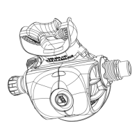
FIRST STAGE FINAL ASSEMBLY
1
With the rst stage still pressurized, insert the hydrostatic transmitter
(23) into the dry chamber and through the adjustment screw (22).
2
Replace the o-ring on the male end of the MP hose. Thread the
hose clockwise by hand into one of the MP ports on the rst
stage. Install the MP test gauge (pn 111610) on the female end of
the hose.
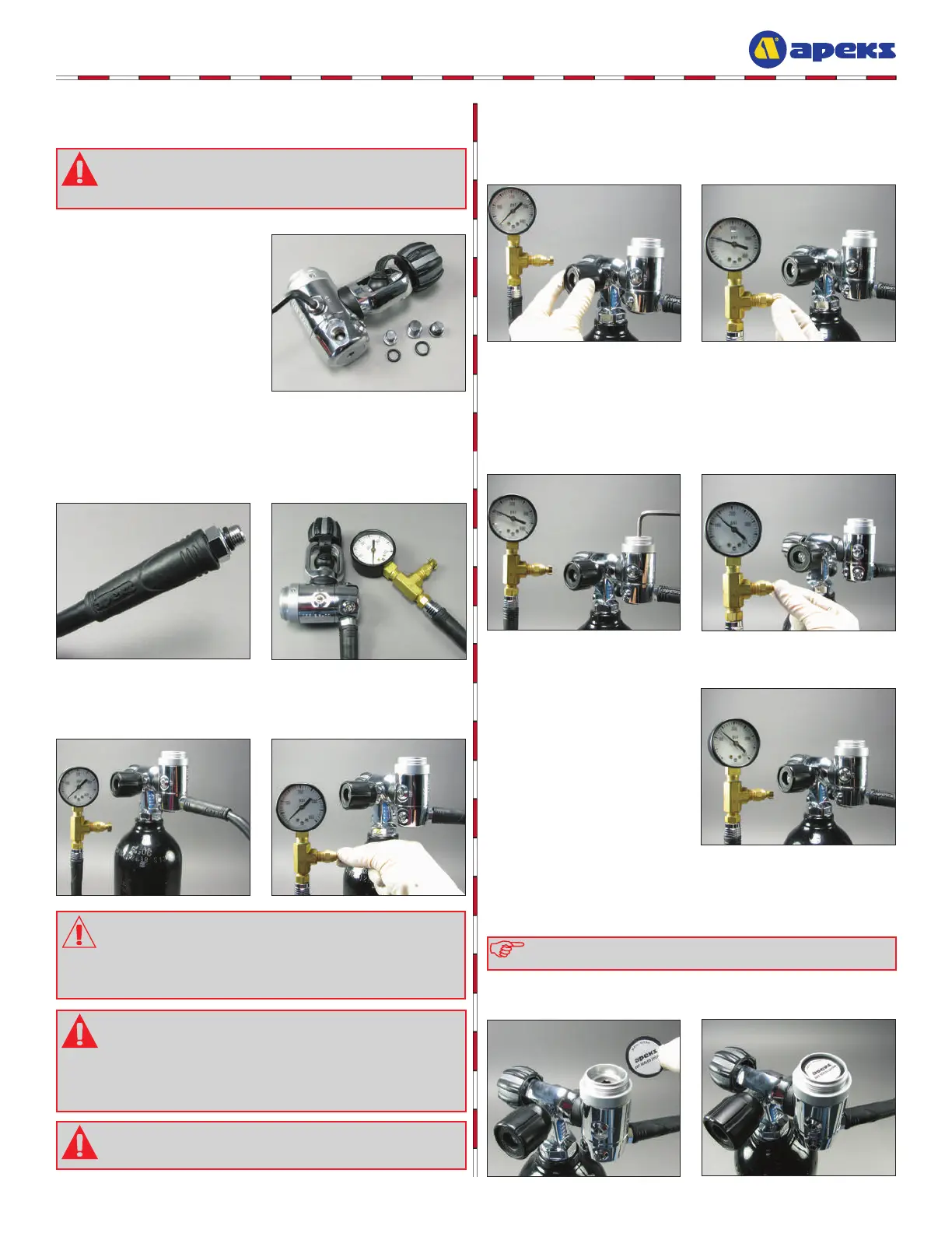
ADJUSTING THE FIRST STAGE
1
Install o-rings (10,13,20) onto
all port plugs (9,18,19). Using
a 5mm hex key, install the port
plugs clockwise into the body and
tighten until snug. Leave 1 MP
port open.