APOGEE ELECTRONICS
8
ROSETTA 800 – User’s Guide
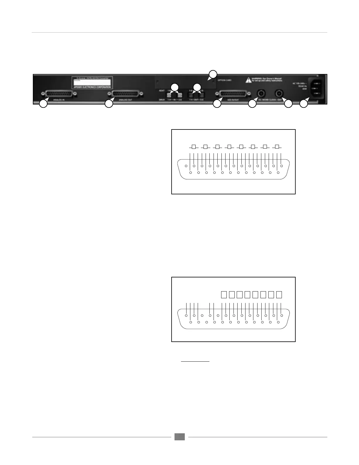
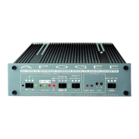
Connections on the Rear Panel
1) ANALOG IN – This DB-25 connection
accepts 8 balanced line-level analog inputs
at a nominal level of +4 dBu =16 dBFs
2) ANALOG OUT - This DB-25 connection
provides 8 balanced line-level analog outputs
at a nominal level of –16 dBFs = +4 dBu.
To set the Analog In/Out to a different
calibration level, please see the
section of this manual entitled “Internal
Adjustments”. The pinout of the Analog
In/Out connectors is compatible with the
Tascam analog cable standard.
3) ADAT – S/MUX IN – These Toslink connections accept ADAT or S/MUX format optical inputs according to
the front panel configuration. When connecting ADAT signals, use the Toslink connection labeled IN 1-8.
When connecting S/MUX signals, use connector “1-4” for the first four channels and connector “5-8” for the
second four channels.
4) ADAT – S/MUX OUT - These Toslink connections provide ADAT or S/MUX format optical outputs
according to the front panel configuration. When connecting ADAT signals, both Toslink connections
provide a duplicate output. When connecting S/MUX signals, use connector “1-4” for the first four channels
and connector “5-8” for the second four channels.
5) OPTION - This slot is reserved for Option
cards, which provide additional input/output
formats, such as FireWire.
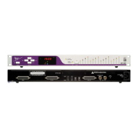
6) AES IN/OUT – This DB-25 connection
accepts 8 channels of AES/EBU digital
input and provides 8 channels of AES/
EBU digital output. When the AES I/O
has been configured for double wide
operation, only the first 4 channels of input
and output are available. The pinout of
the AES IN/OUT connection is compatible
with the Yamaha AES cable standard.
7) WORD CLOCK IN - This BNC connection
accepts a TTL Logic clock signal. The Word Clock In is un-terminated.
8) WORD CLOCK OUT - This BNC connection provides a TTL Logic clock signal output.
9) AC IN - This IES connection accepts an AC input of 100 to 240 VAC at a frequency of 50 to 60 Hz.
1
2
3 4
5
6
7
9
8
10111213
141516171819202122232425
G C H G C H G
C H
G C H G C H G C H G C H G C H
1
2
3
4
5
6
7
8
9 8 7 6 5 4 3 2 1
10111213
141516171819202122232425
GG G G G G
C
H C H C H C H C H C H C H C H
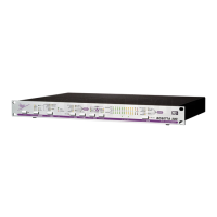
1,2
in
3,4
in
5,6
in
7,8
in
1,2
out
3,4
out
5,6
out
7,8
out
9 8 7 6 5 4 3 2 1
DB-25 pinout for ANALOG IN/OUT
H=HOT C=COLD G=GROUND
DB-25 pinout for AES IN/OUT
H=HOT C=COLD G=GROUND