APOGEE ELECTRONICS
13
ROSETTA 800 – User’s Guide
ANALOG INPUT/OUTPUT CALIBRATION
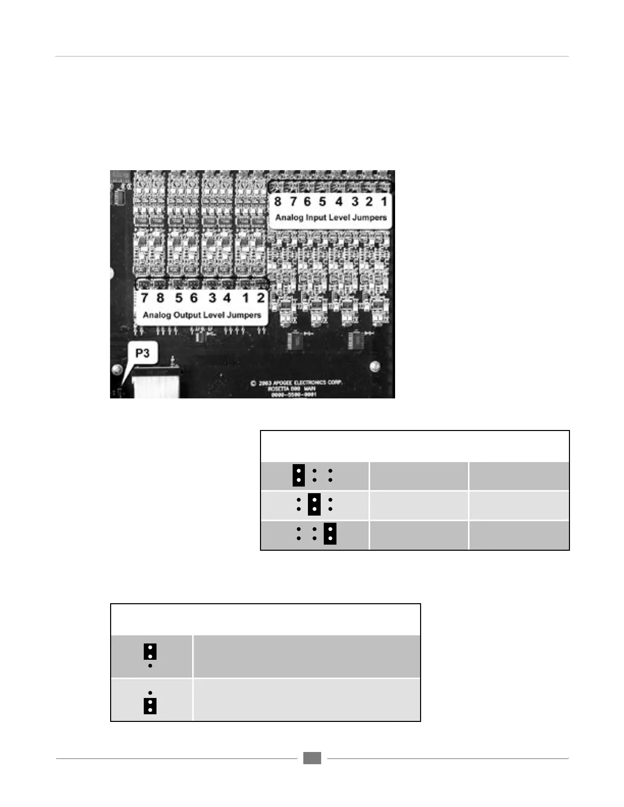
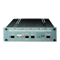
Calibration levels for the Analog Inputs and Outputs are set with internal jumpers. A “block” of 6 jumpers offers 3
level settings for each input and output channel. The locations of these jumpers are indicated in FIGURE 3.
Internal Adjustments
FIGURE 3
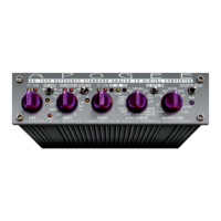
JUMPER
(as seen from front)
ANALOG
Reference Level
DIGITAL
Reference Level
-10 dBV -13 dBfs
+4 dBu -16 dBfs
+4 dBu -20 dBfs
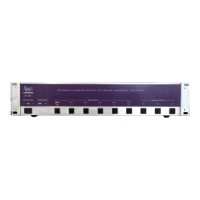
FIGURE 4
JUMPER P3
(as seen from front) DESCRIPTION
When AC power is applied to the input, the unit does not
power up immediately; to power on the unit,the POWER
button must be pressed.
When AC power is applied to the input, Rosetta 800 powers
on immediately; nevertheless, the POWER switch is
functional.
FIGURE 5
POWER SWITCH CALIBRATION
FIGURE 4 depicts the reference
analog and digital levels obtained
when applying a shunt to each
pair of jumpers. For example,
when a shunt is applied to the
middle pair of each input and
output “block”, a +4 dBu analog
input results in a –16 dBFs digital
output, while a –16dBFs digital
input results in a +4 dBu analog
output.