APOGEE ELECTRONICS
5
Symphony PCI card – User’s Guide
Word Clock Connection on Apogee Interfaces
Apogee hardware interfaces connected to the Symphony PCI card must be configured so the units’
clocks are synchronous. This may be accomplished in a number of ways, but the two most simple
clock configurations are shown below in Figures A & B. Note that the depicted clock configurations
are the same for any combination of Apogee interfaces.
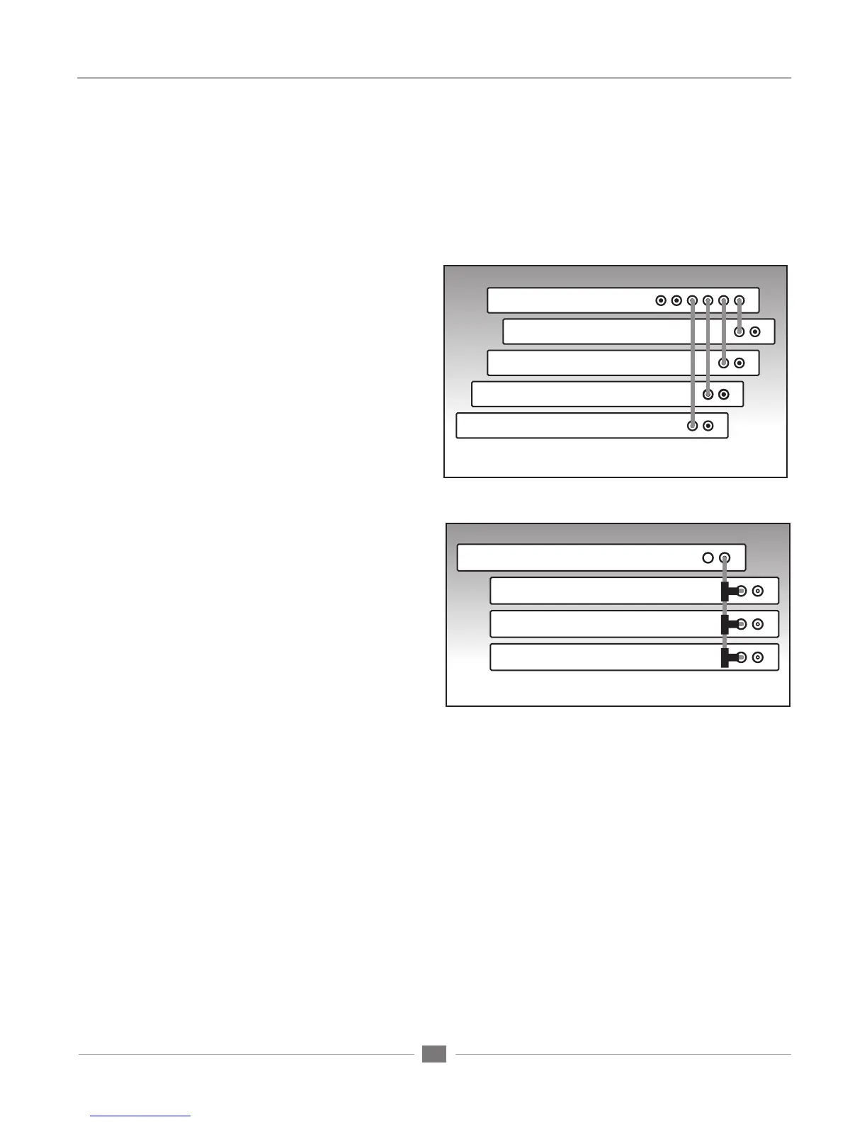
Master Clock:
Connect a word clock cable between out-
puts of a Master clock such as Apogee’s
Big Ben and each interface.
Terminate the word clock input of each
interface.
Set the clock source of each interface to
word clock
BNC “T” Clock Chain:
Set the clock source of the first interface to
internal and connect its word clock output to
a BCN “T” connector on the second inter-
face’s word clock input.
Connect a second cable from the BNC “T”
on the second unit to a BNC ‘”T” on the third
unit’s word clock input.
Make a similar connection between the third
and fourth units.
Terminate the last interface’s word clock
input, either by engaging the 75 ohm termi-
nation switch (AD,DA16X) or by adding a 75
ohm termination plug to the last interface’s
BNC “T” connector.
Figure B. Correct clocking configuration to the master device’s
clock output using BNC “T“ connectors
Figure A. Optimum clocking configuration using BIG BEN
Big Ben
Interface 1
Interface 2
Interface 3
Interface 4
Interface 1
Interface 2
Interface 3
Interface 4