15
Board Actuator Function
Cable
Pin 1 Orange Open Limit
Pin 2 White Close Limit
Pin 3 Black Motor (positive on open, negative on close)
Pin 4 Red Motor (negative on open, positive on close)
Pin 5 Green Common for both limit switches
Pin 6 Yellow Feedback from intelligent actuator (816E/816EX)
Pin 7 Black Battery Negative
Pin 8 Red Battery Positive
1
3
5
7
2
4
6
8
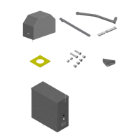
Actuator Connector
12V Supplied battery voltage
SLV Slave Operator Indicator (indicates slave side of gate is closed)
+12V when on closed limit. Ground when off of closed limit.
MAS Master Operator Indicator (indicates master side of gate is closed)
+12V when on closed limit. Ground when off of closed limit.
GND Battery supplied ground
SIREN Connect to siren + (optional)
+12V when gate(s) are running, or in hard shutdown
GND Battery supplied ground
LOCK Connect to lock + (optional) Magnetic or Solenoid type locks (Dip Switch #6 Selectable)
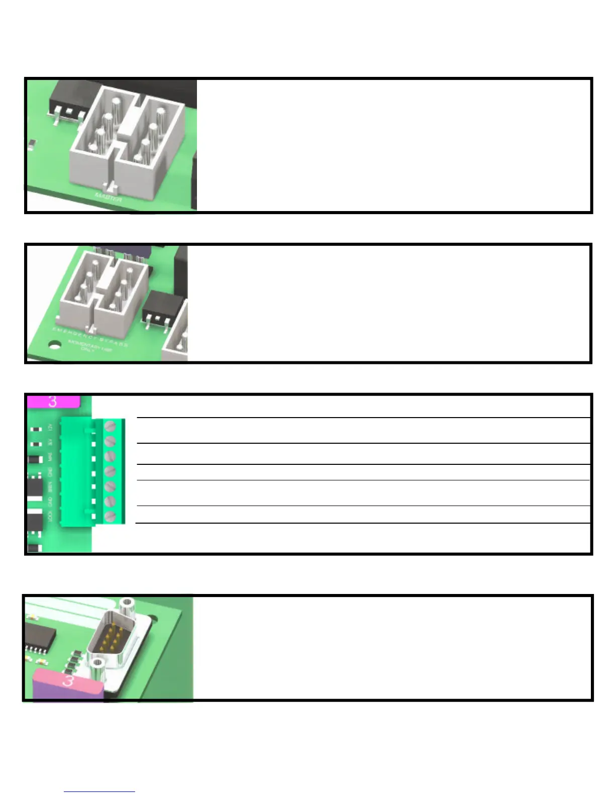
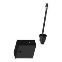
Applies battery voltage directly to motor to open gate if
control board fails. User must unplug before gate opens
to maximum travel or 15 amp fuse will open. Fuse
should be checked before returning gate to service.
EMERGENCY BYPASS
Remote Outputs
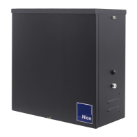
Connects control board to a computer using GateLink software. This software
can monitor and diagnose the functions of the microprocessor. Ask your sales-
person about this feature.
GateLink Connector