10
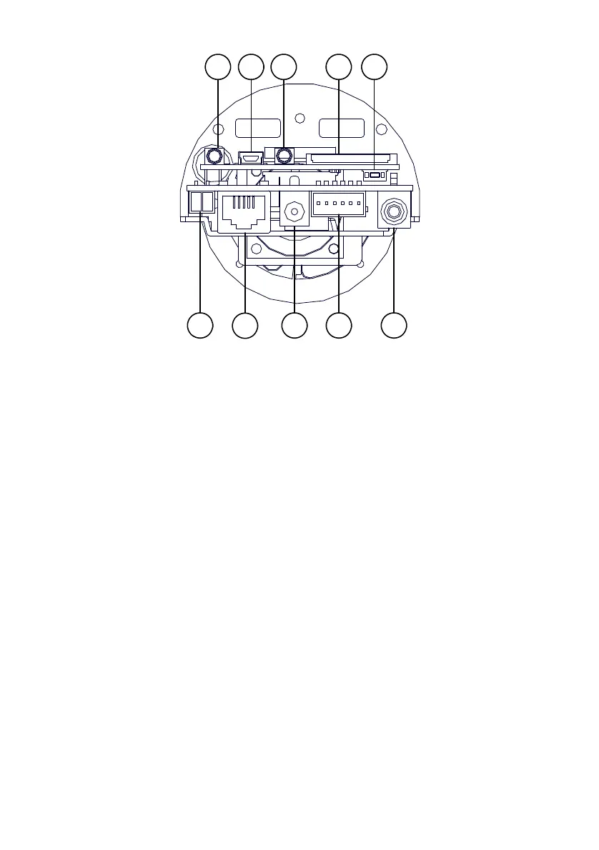
The PCB board:
1
2
3 4 5
6 7 8 9 10
1. Plug Inlet: An AC 24V inlet that connects to an external power supply.
2. ETHERNET 10/100 Connector: This is a standard RJ-45 connector for 10/100 Mbps
Ethernet networks. PoE (Power over Ethernet) function:
Provides power to the device via the
same cable as used for the network connection.
3. Plug Inlet: A DC 12V inlet that connects to an external power supply.
4. GPIO: This is a 6-PIN connector including the Digital output/input, DC output and
GROUND items for connecting with external devices.
5. VIDEO OUT Connector: The connector provides the unit’s composite video signals to a
monitor. (This connector adjusts and improves the images.)
6. AUDIO IN: The connector is used to connect the audio output from other devices to the
camera.
7. USB port: The user can use a USB device cable to connect the IP camera to the USB port on
the PC.
8. AUDIO OUT: Provides the camera’s audio signal to a speaker or stereo.
9. SD/ SDHC CARD slot: This is used for updating system software and archiving / accessing
critical images.
10. RESET: Recover to factory default. (Refer to section 2.4 The Reset Button.)