CHAPTER 3
UNIT DESCRIPTION
Entire Contents Copyright 2004 by Adaptive Power Systems, Inc. (APSI) • All Rights Reserved • No reproduction without written authorization from APSI.
APS-1000 Series 3 - 9 OM-001-01000-000-04.0
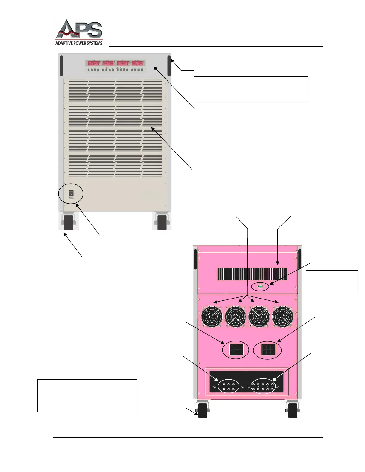
APS-1000 Series Unit (typical)
Front View
Input Power
Circuit Breaker
Terminals
Output Power
Circuit Breaker
Terminals
Instrumentation
Air Vents
External Input
Power Switch
Front Panel Control & Displays
• Frequency
• Voltage
• Current
• Multimeter
DO NOT use handles for lifting.
Lock / Unlock
And Swivel
Fixed Position
Connector location is
The exact configuration of your unit
may be different from the illustration,
depending on the model number.