CHAPTER 6
INSTRUMENTATION CALIBRATION
Entire Contents Copyright 2004 by Adaptive Power Systems, Inc. (APSI) • All Rights Reserved • No reproduction without written authorization from APSI.
APS-1000 Series 6 - 6 OM-001-01000-000-04.0
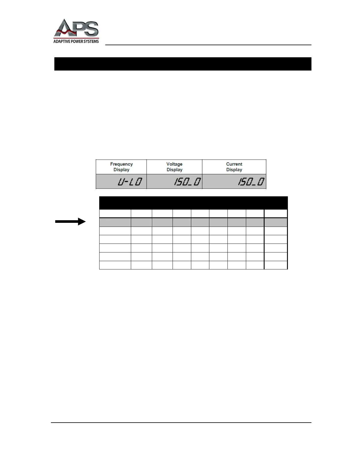
Low-Voltage Mode (U-LO) Calibration
1. At the FREQUENCY Display, press the ︿ or ﹀ buttons to select
Υ−ΛΟ
(V-LO).
The low-voltage parameter is calibrated (first) at the beginning of calibration.
2. At the OUTPUT Terminals, with no load attached, carefully connect a certified,
calibrated RMS voltmeter, of at least 0.2% accuracy, to the output.
3. At the VOLTAGE Display, press the OUTPUT/RESET button. The APS unit will
automatically perform a low-voltage output reading and will output approximately
150 VAC. The external RMS voltmeter will display the actual voltage output, and
the current display will show the calibration value (see Calibration Table below).
Calibration Settings
V HI (VAC) 300.0 300.0 300.0 300.0 300.0 300.0 300.0 300.0
A LO (A) 3.000 3.000 30.00 30.00 30.00 30.00 30.00 300.0
A HI (A) 16.00 25.00 42.00 80.00 160.0 250.0 330.0 500.0
4. At the CURRENT Display Adjust the voltage using the CURRENT ︿ or ﹀
buttons until the metered values match.
5. At the CURRENT Display, press the LOCK button to finish low-voltage calibration.
6. Proceed to the next calibration function, unless this completes system calibration.
7. Note, to exit the Calibration Mode, your APS system must be restarted after you
have completed ALL calibration operations.