CHAPTER 1
INTRODUCTION
Entire Contents Copyright 2004 by Adaptive Power Systems, Inc. (APSI) • All Rights Reserved • No reproduction without written authorization from APSI.
APS-1000 Series 1 - 8 OM-001-01000-000-04.0
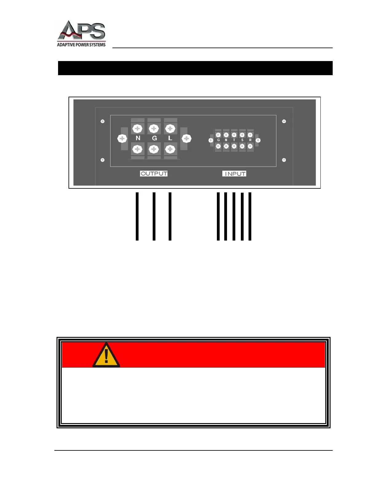
Example Wiring Diagram
INPUT / OUTPUT Power Panel at Rear of APS Unit (typical)
WARNING
THIS EQUIPMENT CONTAINS HIGH ENERGY, LOW IMPEDANCE CIRCUITS!!
LETHAL POTENTIALS ARE CONTAINED WITHIN THE CABINET.
ONLY FULLY-QUALIFIED PERSONNEL SHOULD ATTEMPT TO MAKE INPUT
OR OUTPUT POWER CONNECTIONS.
OUTPUT CONNECTIONS INPUT CONNECTIONS
NOTE: Input Terminal Phases R, S, T are North American (U.S.) A, B, C
NOTE: Other terminal configurations are possible. For example, there is
no neutral terminal for 3-phase delta-winding inputs. In addition,
depending on voltage range, there may be no neutral terminal. All units
provide 1-phase outputs. Inputs are 3-phase, except for APS-1002, APS-
1003, and APS-1005, which have 1-phase inputs (2-wire plus ground).