CHAPTER 6
INSTRUMENTATION CALIBRATION
Entire Contents Copyright 2004 by Adaptive Power Systems, Inc. (APSI) • All Rights Reserved • No reproduction without written authorization from APSI.
APS-1000 Series 6 - 10 OM-001-01000-000-04.0
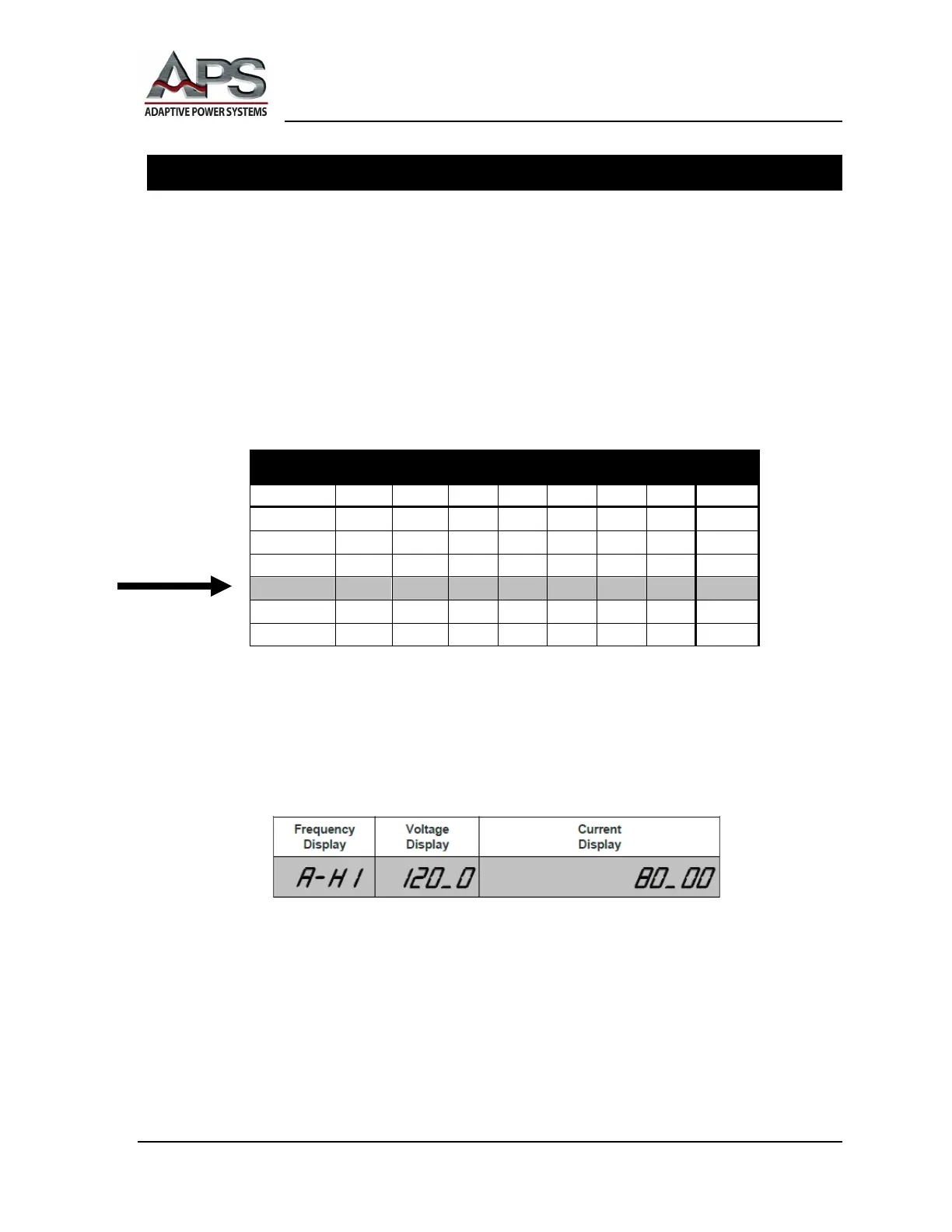
High Current (A-HI) Mode Calibration
1. At the FREQUENCY Display, press the ﹀ button to select
Α−ΗΙ
(A HI).
2. At the OUTPUT Terminals, carefully connect a resistive load and connect a
certified, calibrated RMS ammeter, of at least 0.2% accuracy.
3. The size of the resistive load should be calculated based on the high-current
parameter for your particular APS unit, as shown in the following Calibration
Table. Use 120 VAC for the voltage.
4. An example calculation is shown on page 6-2 in the Section Calculation Setup,
subsection How to Calculate the Size of the Load.
Calibration Settings
V LO (VAC) 150.0 150.0 150.0 150.0 150.0 150.0 150.0 150.0
V HI (VAC) 300.0 300.0 300.0 300.0 300.0 300.0 300.0 300.0
P HI (kW) 2.000 3.000 5.000 9.000 18.00 27.00 36.00 54.0
5. At the VOLTAGE Display, press the OUTPUT/RESET button. The APS unit
will automatically perform a high-current output reading and will output
approximately 120 VAC.
6. The external RMS ammeter will display the actual current output. The
CURRENT Display shows the calibration value (see Calibration Table, above).
7. Adjust the load or the output voltage until the RMS ammeter displays the value
shown in the Calibration Table (above). Please note, the value for your unit will
depend on the model.