APsystems Microinverter EZ1 series User manual
4. APsystems Microinverter System Installation
When plugging in the DC cables, the microinverter should immediately blink green ten times. This will happen as
soon as the DC cables are plugged in and will show that the microinverter is functioning correctly. This entire check
function will start and end within 10 seconds of plugging in the unit, so pay careful attention to these lights when
connecting the DC cables.
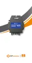
Figure 4
Each PV panel must be carefully connected to the same channel.
Make sure to not split positive and negative DC cables into two different input channels: microinverter will become
damaged and warranty will not apply.
4.2.4 Step 4 - Connect the APsystems microinverter to EU power cord
Insert the microinverter AC connector into the power cord connector.
Figure 5
4.2.5 Step 5 - Cable Connection
Insert the power cord into the socket.
Figure 6