EasyManua.ls Logo

Aqualisa AQ75 - User Manual

Aqualisa AQ75
20 pages
Print Icon
To Next Page IconTo Next Page
Loading...
AQ75
AQ100
3245F
Thermostatic bar mixer valve
with adjustable head
Installation guide
AQ100 AQ75:Midas 8/9/15 13:53 Page 1
Question and Answer IconNeed help?

Do you have a question about the Aqualisa AQ75 and is the answer not in the manual?

Summary

Important Information and Product Overview

Introduction to Aqualisa Bar Valve

Overview of the Aqualisa bar valve mixer, its features, suitability, and guarantee.

Safety Information for Installation

Emphasizes installation by a competent person following Water Supply Regulations.

Product Specifications and Requirements

Details suitability for various systems, pressure range, and combination boiler requirements.

Connection Guidelines

Specifies HOT on Left, COLD on Right and the need to flush supply lines before installation.

System Requirements and Gravity Feed

Flushing, Filters, and Isolating Valves

Instructions for flushing, filter maintenance, and fitting suitable isolating valves.

Pressure Limits and Gravity System Siting

Details pressure requirements, PRV recommendations, and optimal siting for gravity systems.

Pumped and High-Pressure Systems

Pump Installation and Water Storage

Guidelines for pump installation and minimum stored water capacities for optimal function.

Balanced High-Pressure and Combination Boiler Systems

Details suitability for high-pressure and combination boiler systems, including specific requirements.

Typical System Diagrams

Gravity System Installation Diagram

Illustrates the typical installation layout for a gravity-fed hot water system.

Pumped System Installation Diagram

Illustrates the typical installation layout for a pumped hot water system.

More System Diagrams

Combination Boiler System Diagram

Illustrates the typical installation for a combination boiler system.

UVHW and Thermal Storage System Diagrams

Illustrates typical installations for UVHW and thermal storage unit systems.

Bar Valve Components Overview

Aqualisa AQ75 Bar Valve Components

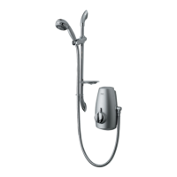
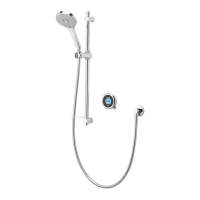
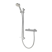
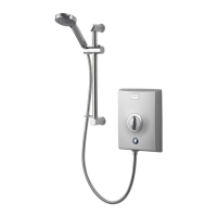
Details the components included with the Aqualisa AQ75 bar valve with adjustable height head.

Aqualisa AQ100 Bar Valve Components

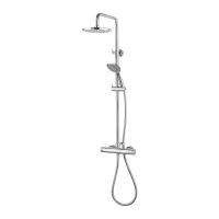
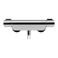
Details the components included with the Aqualisa AQ100 bar valve with adjustable height head.

Aqualisa 3245 F Bar Valve Components

Components of 3245 F Bar Valve

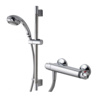
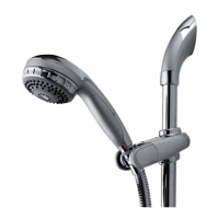
Details the components included with the Aqualisa 3245F bar valve with adjustable height head.

Bar Valve Installation Guide

General Installation Precautions and Competency

Essential pre-installation checks, competency, and adherence to regulations.

Fixing Accessories and Pipework Preparation

Guidance on using fixing accessories, pipework adjustment, and thread preparation.

System Flushing and Pressure Testing

Steps for flushing the system, pressure testing, and protecting connections from ingress.

Aqualisa AQ75 Adjustable Height Head Installation

Cover Plate and Valve Attachment

Steps for fitting cover plates to the wall and attaching the valve with fibre washers.

Hose Connection and Initial System Flush

Connects the hose and flushes the system; refers to commissioning for temperature adjustment.

Rail and Handset Holder Assembly

Instructions for assembling the adjustable height rail and fitting the handset holder.

Aqualisa AQ75 Rail Securing and Hose Connection

Securing Rail Assembly and Covers

Steps for fitting the rail into end bodies, securing to the wall, and fitting covers.

Optional Flow Regulators and Hose Connection

Guidance on fitting optional flow regulators and connecting the hose to the valve outlet.

Handset Securing and Holder Tension Adjustment

Instructions for securing the handset to the hose and adjusting handset holder tension.

Aqualisa AQ100 Adjustable Height Head Installation

Handset Holder and Wall Bracket Preparation

Steps for installing the handset holder onto the rail and preparing wall brackets.

Securing Rail Assembly to Wall Brackets

Instructions for sliding and securing the rail assembly onto the wall brackets.

Aqualisa 3245 F Adjustable Height Head Installation

Drilling and Bracket Fitting for 3245 F

Steps for drilling holes, fitting bottom and top rail brackets for the 3245F model.

Placing Rail Assembly and Covers

Instructions for placing the rail assembly onto brackets and fitting rail end covers.

Aqualisa 3245 F Final Assembly and Hose Connection

Handset Securing and Tension Adjustment

Instructions for securing the handset and adjusting handset station tension.

Handset to Hose Assembly Procedure

Steps for passing the hose through the restraint and securing the handset to the hose.

User Guide and Maintenance

Operating Shower Controls

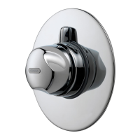
Guide on using temperature and flow control knobs, including maximum temperature setting.

Adjusting the Shower Head

Instructions for adjusting the height and angle of the shower head on the rail.

Cleaning and Descaling Advice

Guidelines for cleaning the bar valve system and descaling the shower head.

Aqualisa Bar Valve Commissioning

Commissioning Overview and Temperature Setting

Details the procedure for setting the maximum shower temperature, recommending 46°C.

Step-by-Step Commissioning Procedure

Detailed steps for adjusting the temperature control, setting max temp, and refitting the knob.

Trouble Shooting Guide

Common Issues, Causes, and Actions

Lists common symptoms like no hot water, poor flow, and temperature swings with possible causes and actions.

Company Information and Contact

Aqualisa Contact Details and Website

Provides contact details, helpline numbers, website, and email for Aqualisa Products Limited.

Quality Marks and Legal Notices

Includes ISO9001 certification, UKAS quality management, part number, and copyright notices.

Overview

The Aqualisa AQ75, AQ100, and 3245F are thermostatic bar mixer valves with adjustable height shower heads, designed for domestic use. These products are supplied with a 3-year guarantee.

Function Description:

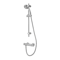
The Aqualisa bar valve is an exposed bar valve mixer that provides close temperature stability and fail-safe protection. The adjustable height shower head features variable spray patterns, allowing users to customize their showering experience. The thermostatic valve ensures a consistent water temperature, preventing sudden changes that could be uncomfortable or unsafe.

Important Technical Specifications:

  • System Compatibility: Suitable for gravity stored, gravity boosted, balanced high pressure, and combination boiler systems.
  • Pressure Range: 0.1 bar (static) minimum to 10 bar (static) maximum.
    • Note on 0.1 bar: This equates to approximately 1m measured from the top of the head to the bottom of the cold water tank, or 1.5m if measured from the top of the head to the top of the water level within the tank. Slow refill of the tank will affect shower outlet flow rate performance.
  • Combination Boiler Requirements: If used with a combination boiler, the boiler MUST have a minimum rating of 24kW (80,000 Btu) and be of the type fitted with a fully modulating gas valve.
  • Connections: Designed for conventional supplies with HOT on the Left and COLD on the Right as viewed from the front.
  • Pressure Reducing Valve (PRV): Where pressures are likely to exceed 5 bar, a PRV must be fitted into the incoming mains supply. A setting of 3 bar is recommended.
  • Gravity Fed Systems:
    • Cold supply for the valve assembly must be taken directly from the cold storage system.
    • Hot supply may be taken from the vent/draw-off pipe of the hot water cylinder at a point below the cylinder connection or from the underside of the horizontal draw-off.
    • Rising pipework must not be connected into the horizontal draw-off from the cylinder or to any point in the vent/draw-off pipe above the cylinder connection.
    • Cylinder temperature in excess of 65°C may result in poor shower performance.
    • To minimize pressure loss, 22mm hot and cold supplies are recommended as close as possible to the mixing valve before reducing to 15mm.
    • Minimum distance between the bottom of the storage cistern and the shower head should not be less than 1m (for adjustable height shower kits).
  • Pump Installation: A pump must only be used to boost pressure from tank-fed supplies. A minimum 1.5 bar twin-ended booster pump may be fitted, though a pump larger than 1 bar is recommended. Pumps must NOT be fitted directly to the water main.
  • Stored Water Capacities: Minimum cold storage cistern capacity should be not less than 225 litres (50 gallons). Hot cylinder capacity must meet anticipated demand.
  • Balanced High-Pressure Systems: Operates with unvented hot water storage systems up to 10 bar. Cold water supply must be drawn from the same mains supply as the hot water system (downstream of the cylinder manufacturer's pressure limiting valve, if supplied). Hot supply from the nearest convenient draw-off point.
  • Maximum Outlet Temperature: The product is pre-set to a safe maximum shower temperature. It is recommended that the maximum outlet temperature is set to 46°C during commissioning.

Usage Features:

  • Temperature Control: The temperature lever knob on the right side of the valve (when viewed from the front) controls the water temperature. The maximum temperature override button is at the top of the knob. Depressing the button allows for temperature adjustment: rotating away from the wall increases temperature, and rotating towards the wall decreases it.
  • Flow Control: The flow control knob on the left side of the valve (when viewed from the front) adjusts the water volume. Rotating towards the wall increases flow, and rotating away from the wall stops the flow.
  • Adjustable Shower Head Height: To select the preferred height, depress the handset holder button fully to move the slider up or down the rail.
  • Angular Shower Head Adjustment: The shower head's angle can be adjusted by carefully pulling it forwards or pushing it back against the knuckle in the holder.
  • Handset Tension Adjustment: The tension of the handset station is factory set but can be adjusted by tightening or loosening the fixing screw inside the handset station using a suitable screwdriver. This may be necessary for high-pressure systems.

Maintenance Features:

  • Flushing: Prior to connection, all soldering must be completed, and pipework thoroughly flushed out to prevent corrosive fluxes from attacking internal parts.
  • Filters: Inlet filter assemblies are integrated into the internal waterways to protect against debris. Accumulation of debris can reduce flow and cause noisy operation. It is suggested that the cartridge be removed and filters checked by a competent person at least every 12 months.
  • Cleaning: The shower system should be cleaned using only a soft cloth and washing-up liquid. Abrasive cleaners must NOT be used.
  • Descaling: The shower head incorporates a 'clear flow' system where scale build-up can be broken down by gently rubbing the flexible tips of the jets. This should be done regularly, especially in hard water areas, as scale can affect spray patterns and performance. Failure to descale may affect internal seals and the warranty. If chemical descaling is necessary, the shower head should be fully removed and immersed in a mild proprietary descalent, strictly following the manufacturer's instructions. Substances not suitable for plastics and electroplated surfaces must be avoided.

Aqualisa AQ75 Specifications

General IconGeneral
BrandAqualisa
ModelAQ75
CategoryPlumbing Product
LanguageEnglish

Related product manuals