Visage Digital concealed installation instuctions page 6
Step-by-step instructions
In addition to the guide below it is essential that the written instructions
opposite are read and understood and that you have all the necessary
components (shown overleaf) before commencing installation. Failure to
install the product in accordance with these instructions may adversely affect
the warranty terms and conditions. Do not undertake any part of this
installation unless you are competent to do so. Prior to starting ensure that
you are familiar with the necessary plumbing regulations required to install
the product correctly and safely.
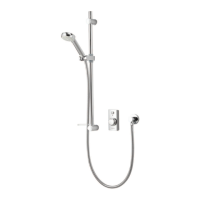
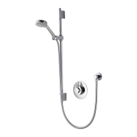
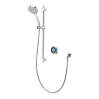
Visage Digital is supplied with universal fittings intended to secure it to a
suitable wall.
!
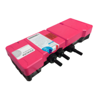
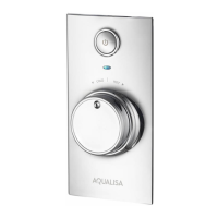
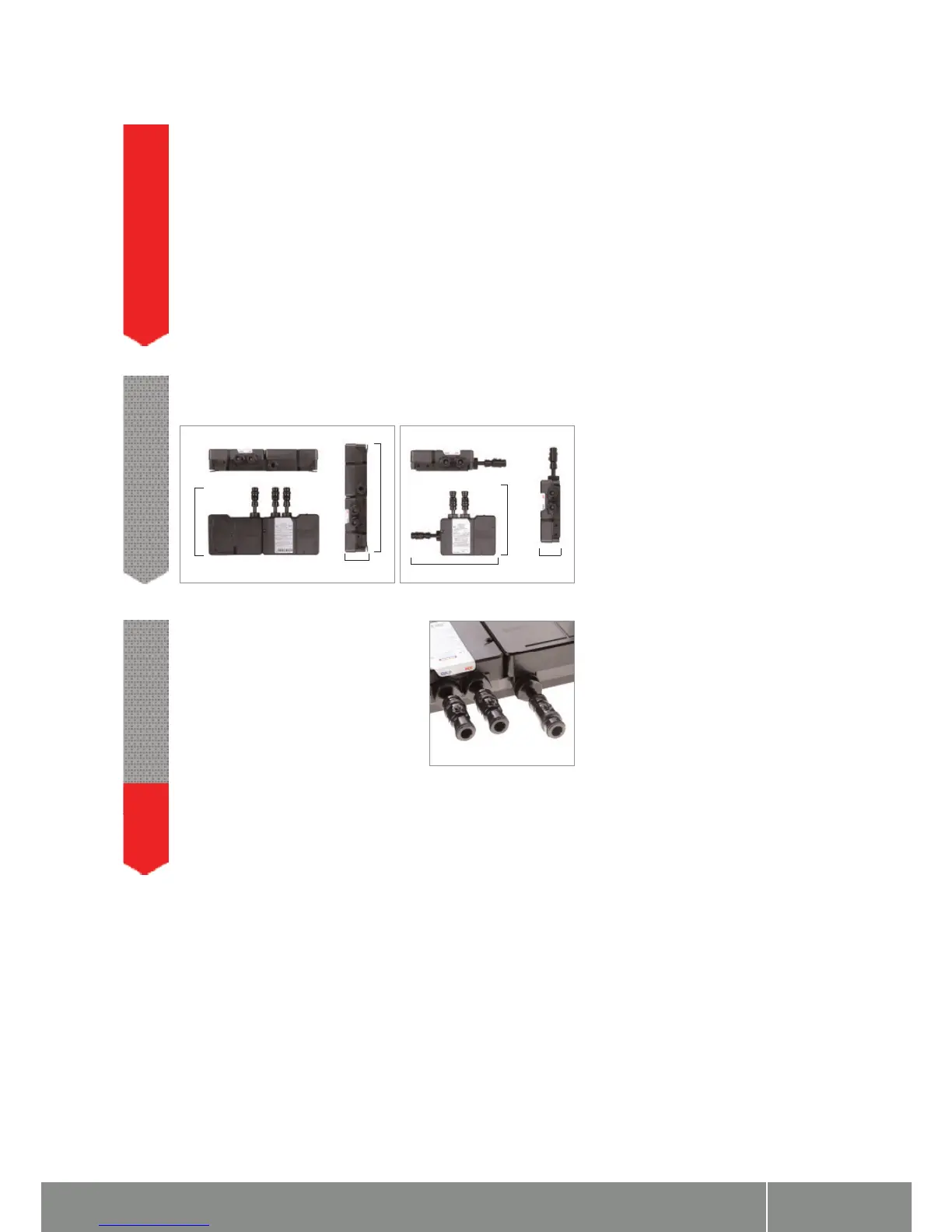
Isolation valves are supplied with the Digital
processor and must be fitted on both inlets
and the blended water outlet. All pipe work
should be run in 15mm pipe. All pipe work
should be supported. For externally pumped
gravity fed installations, 22mm pipe work
should be run as close to the processor as pos-
sible before reducing down to 15mm.
2
The inlet supply centres are 48mm. The inlet supply centres deviate from
EN1111 and EN1287, but are deemed to be a special case.
Please note arrow on isolation valve to indicate direction of flow.
!
90mm
445mm
270mm
350mm
265mm
70mm
To ensure safe operation and installation of this product, the processor MUST be
installed in one of the orientations shown.
1