E
N
G
before engaging the work piece.
6. Never start or operate the tool with fingers or
other objects through the holes in the blades.
7. Use care when handling blades during and
after use. The blades and some areas of the tool
become hot in use.
8. Always ensure that before cutting there are
no hazards such as electrical wiring, pipes or
insulation in the area to be cut.
9. Allow for resting periods to ease the effect
of the vibration of the tool. Use work gloves to
minimise vibration effect on the body.
10. Ensure the dust extraction equipment is
connected and properly used.
11. Keep handles dry, clean and free from oil and
grease.
12. If the guard or other parts appears to be
damaged, it should be carefully checked to
determine that it will operate properly and perform
its intended function.
13. The use of any accessory or attachment other
than those recommended in this instruction manual
maypresentariskofpersonalinjury.
14. Do not force the tool. It is designed to
operate with moderate effort. Overheating of the
drive system and motor can occur if the tool is
overloaded.
15. Always operate the tool holding it with both
hands.
SYMBOLS The following show the symbols used
in this manual
Class 2 Construction (Double
Insulation used throughout, no
provision for earthing.)
VAC volts alternating current
A amperes
Hz hertz
W watt
N
0
no load speed
rpm revolutions per minute
dB decibels
Nm newton meters
m meters
SYMBOLS The following show the symbols used
in this manual
m/s meters per second
mm millimeters
kg-m kilogram meters
ft-lb foot pounds
4. FUNCTIONAL DESCRIPTION
4.1 AS170 TOOL DESCRIPTION
The AS170 is designed to cut rigid materials
suchasmortar,clayredbricks,plasterboard,
breboard,weatherboardandwood.TheAS170
uses a variety of blades to suit the material being
cut. Blades may also be changed to suit the
required depth or length of cut.
The blades are driven via conrods and a camshaft,
which is belt-driven. The V-belt is designed to allow
someslipincaseofthebladesjamming.The belt
tension must be checked after the first 5 hours
of use. It is easily tightened by removing the plastic
coverandistensionedusingtheadjustableidler
pulley (see section 7.2).Blades are mounted to the
conrods using high tensile Allen™ head bolts.
A replaceable metal guard is provided to limit the
maximum cutting depth and prevent the blade
mounts from damaging the surface of the material
being cut. Shock and vibration to the operator are
reduced by a rubber-mounted top handle. The top
handle is also designed for comfort when used in
a variety of cutting orientations. The rubber bushes
on the top handle can be replaced if they become
worn or damaged.
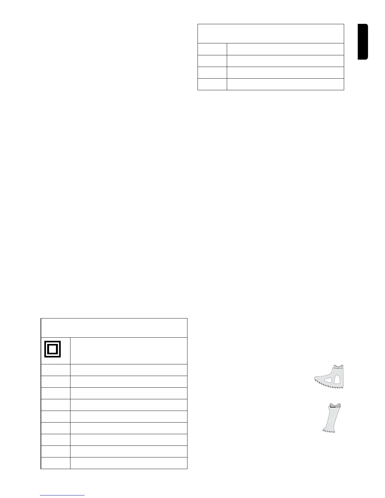
4.2 BLADE DESCRIPTION
The AS170 uses a variety of blades to cut different
materialsanddifferentproles.
General Purpose blades use Tungsten
Carbide teeth and are suited for working
generalmasonryand“intheground”cutting.
General Purpose blades are designed to cut
to a depth of 115mm (4 1/2”).
Plunge blades use Tungsten Carbide teeth
and have a maximum cutting depth of
120mm (
4
3/4
”). Mortar plunge blades can cut
slots of 75mm (3”) in length.
eNGLISH 4
 Loading...