Optima 70 - 2 22
VENTING - HORIZONTALLY USING SIMPSON DURA-VENT DIRECT VENT SYSTEMS
1. Set the Optima 70 in its desired location.
Determine if wall studs or roof rafters
are in the way the when venting system
is attached. You may want to adjust the
location of the unit to compensate.
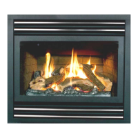
2. Simpson Dura-Vent Venting System is
designed with special twist-lock connec-
tions to connect to the appliance. An
Archgard adaptor (SDA-3) is required.
The adaptor will allow Simpson Dura-
Vent System to be used.
3. Apply a bead of silicone inside the outer
section of the SDA-3 adaptor (crimped
side). Slip the adaptor over the existing
inner and outer flue collar and fasten it
to the outer collar only with 3 screws
(drill pilot holes first). Level the appli-
ance and fasten it to the framing using
nails or screws through the nailing
strips.
4. Assemble the desired combination of
pipe and elbows to the appliance adap-
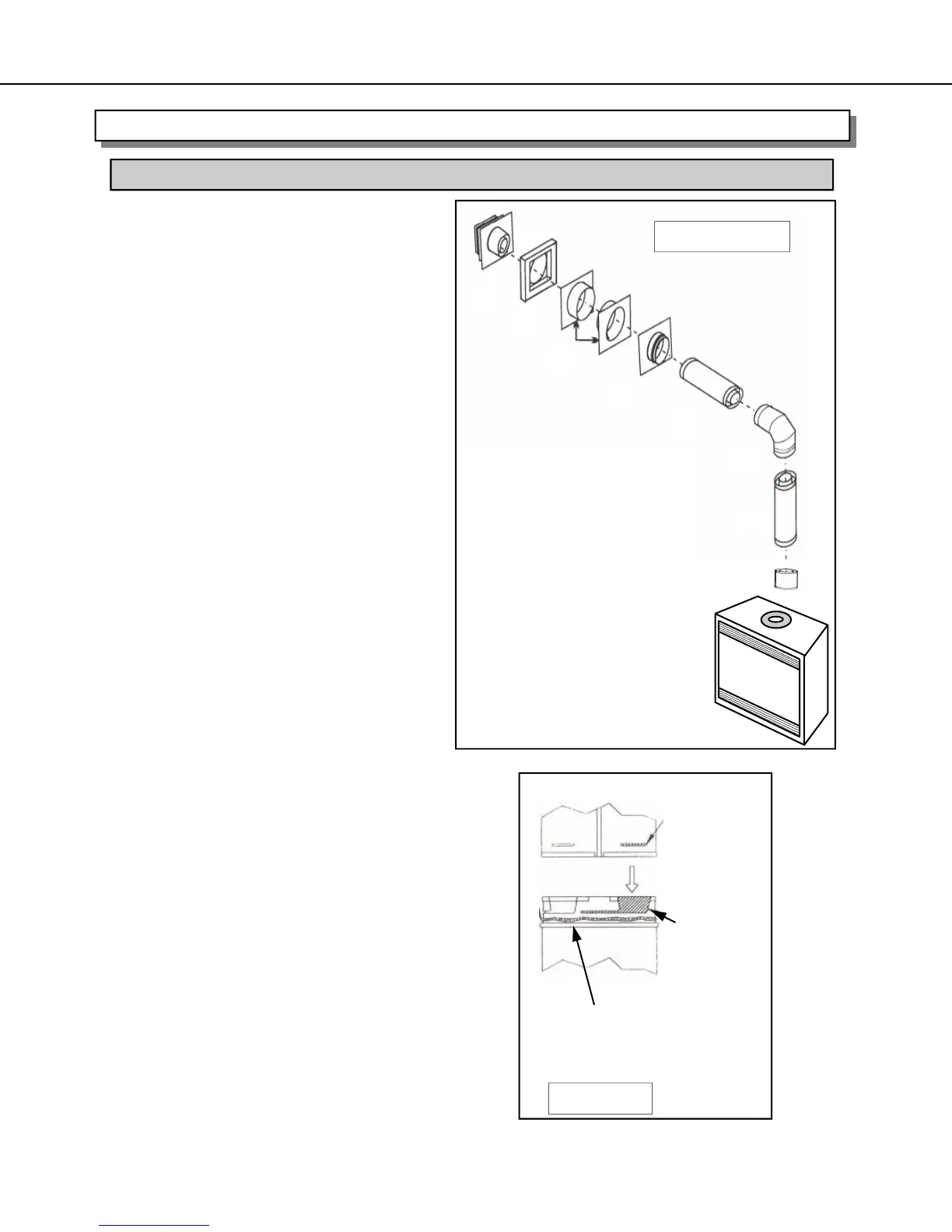
tor and twist lock the pipe. NOTE:
Twist-lock procedure: Four indentations,
located on the female ends of the pipes
and fittings, are designed to slide
straight onto the male ends of adjacent
pipes and fittings by orientating the four
pipe indentations so they match and
slide in to the four entry slots on the
male ends (Fig. 2.). Push the pipe sec-
tions completely together, then twist-lock
one section clockwise approximately
one quarter turn, until the two sections
are fully locked. The female locking lugs
will not be visible from the outside, on
the pipe or fittings. They may be located
by examining the inside of the female
ends. Horizontal vent runs MUST be
supported every three feet (76 mm).
Wall straps are available for this pur-
pose.
NOTE: Follow venting horizontal venting
chart and Allowable Termination locations
guidelines.
INSTALLATION PROCEDURES FOR SIMPSON DURA-VENT DIRECT VENT SYSTEM
Female
Locking
Lugs
Sealant
Male Lock-
ing Lugs
Fig. 2.
#1
#2
#3
#4
#5
#6
#7
#8
Fig. 1.
#1. Vertical Termination
#2. Vinyl Siding Standoff
(Optional)
#3. Wall Thimble
#4. Round Support Box
#5. Adj. Length of pipe
#6. 90
0
Elbow
#7. Pipe Length
#8. SDA-3 Adaptor 3” (76 mm)
Refer to Venting Chart on Page 15