VIPER Detailed hardware description
© 2004 Arcom Issue H 27
ICR Bit Functions
Bit Name Value Function
0 No interrupt retrigger (embedded Linux and VxWorks).
0 RETRIG
1 Interrupt retrigger (Windows CE .NET).
0 No auto clear interrupt / Toggle GPIO1 on new interrupt.
1 AUTO_CLR
1
Auto clear interrupt / Low to high transition on GPIO1 on
First Interrupt.
0
2 R_DIS
1
Keep set as 0 under normal operating conditions. See
the section Power management, page 52 for details.
3 - 7 - X No function.
PC/104 interrupts under embedded Linux and VxWorks
Leave the ICR register set to its default value, so that a new interrupt causes the
microprocessor PC/104 interrupt pin GPIO1 to be toggled for every new interrupt on a
different PC/104 interrupt source. Ensure the GPIO1 input is set up in a level triggered
mode. The retrigger interrupt function is not required for embedded Linux or VxWorks.
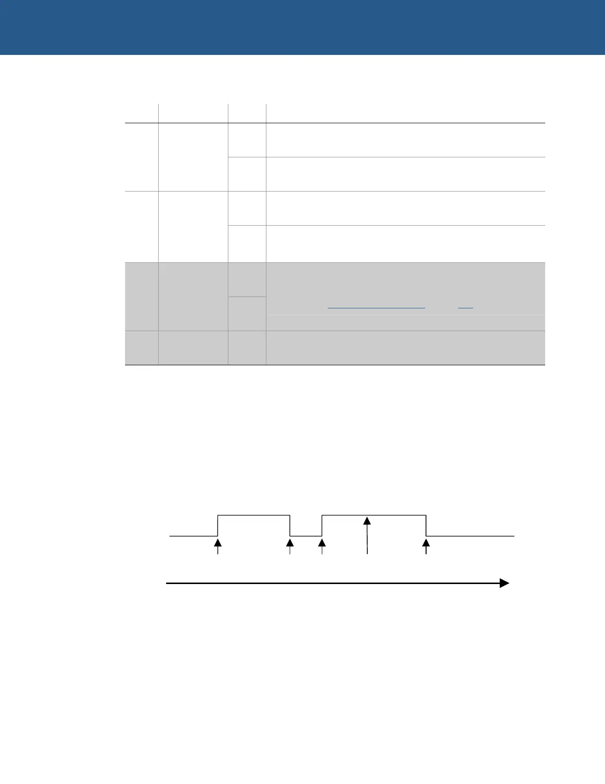
The following diagram gives an example of how the PC/104 interrupt on GPIO1
behaves over time when the ICR AUTO_CLR bit is set to ‘0’:
Once the VIPER microprocessor has serviced a PC/104 interrupt, clear the
corresponding bit in the PC104I register by writing ‘1’ to it.
1
s
IRQ
on IRQ7
1
s
IRQ
on IRQ5
1
s
IRQ
on IRQ12
2
n
IRQ
on IRQ7
GPIO1
Level
Time
1
s
IRQ
on IRQ7
serviced