18
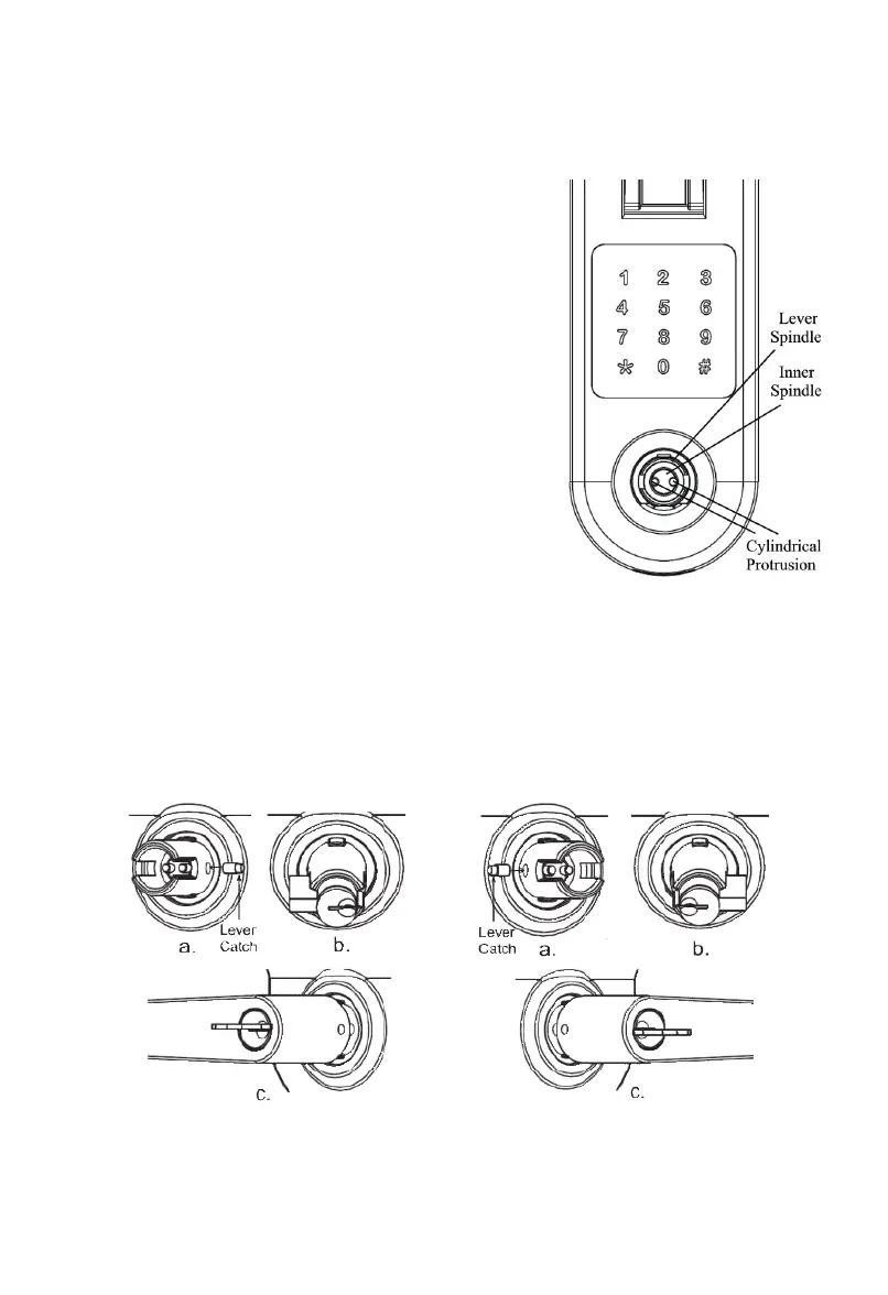
fig. 7
fig. 8
3.4 Insert Cylinder in Lever Spindle. The Cylinder’s tail
toward left if you want to set lock as left-handed (see fig.
7b), otherwise the Cylinder’s tail toward right (see fig. 8b).
3.5 Put lever on Lever Spindle (see fig. 7c, 8c). The lever
will stop at half way when you push Lever in. Insert key
into Cylinder, push the lever (see fig. 9b) and rotate the key
CLOCKWISE until the lever is pushed in. Key should be
rotated around 90° but could be up to 135° (see fig. 9a).
Rotate the key counter CLOCKWISE (see fig. 9c) then take
the key out (see fig. 9d).
3.6 Remove Lever (if necessary): Insert key into Cylinder
then rotate key CLOCKWISE 90°, use Allen Wrench or
paper clip to push Lever Catch in then pull lever out (see
fig.10). Rotate key COUNTER CLOCKWISE 90° then
take key out. Use Flathead Screwdriver to rotate
Cylindrical Protrusions, the Lever Catch will protrude.
Take the Lever Catch out, keep it in safe place.
3.7 Switching Levers (if necessary): Levers can be reversed
to extend toward hinges. Refer 3.6 to remove lever then
following 3.1 to 3.5 to set up lever.