Supplied By www.heating spares.co Tel. 0161 620 6677
50
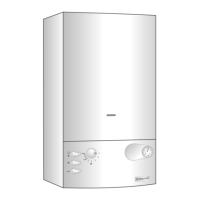
Fig. 102
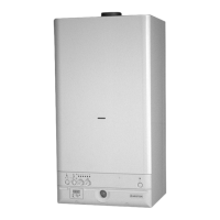
Fig. 101
V
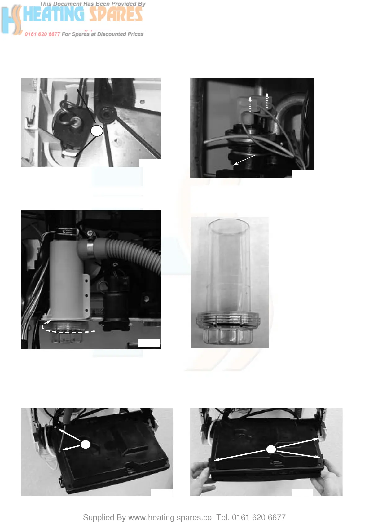
Fig. 105
W2
W1
18.3.12 Removing the pressure switch
1. Remove the casing as in step 18.1.1 and drain down as
in step 18.3.1;
2. Pull off the connections. Then remove the pressure
switch by releasing it’s securing clip (see Fig. 102).
18.3.11 Removing the pressure gauge
1. Carry out steps 18.1.1 and 18.3.1;
2. Remove the pressure gauge by releasing the two clips V
and pulling the pressure gauge out. (see Fig. 101)
18.4 Access to the Control System
18.4.1 Removing the P.C.B.s
3. Release the three clips W2 and remove the electrical box
cover (see Fig. 106);
1. Carry out steps 18.1.1 and 18.1.2;
2. Remove the two screws W1 from the electrical box (see
Fig. 105);
Fig. 104
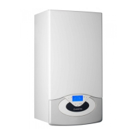
Fig. 103
18.3.13 Removing & cleaning the condensate trap
1. Unscrew the cap of the condensate trap (see Fig. 103)
2. Empty the condensate products and rinse the
condensate trap with clean water (see Fig. 104)
3. Reassemble in reverse order and fill the condensate trap
with 1/2 litre of water before restarting the boiler.
Fig. 106

 Loading...