12
3. installation
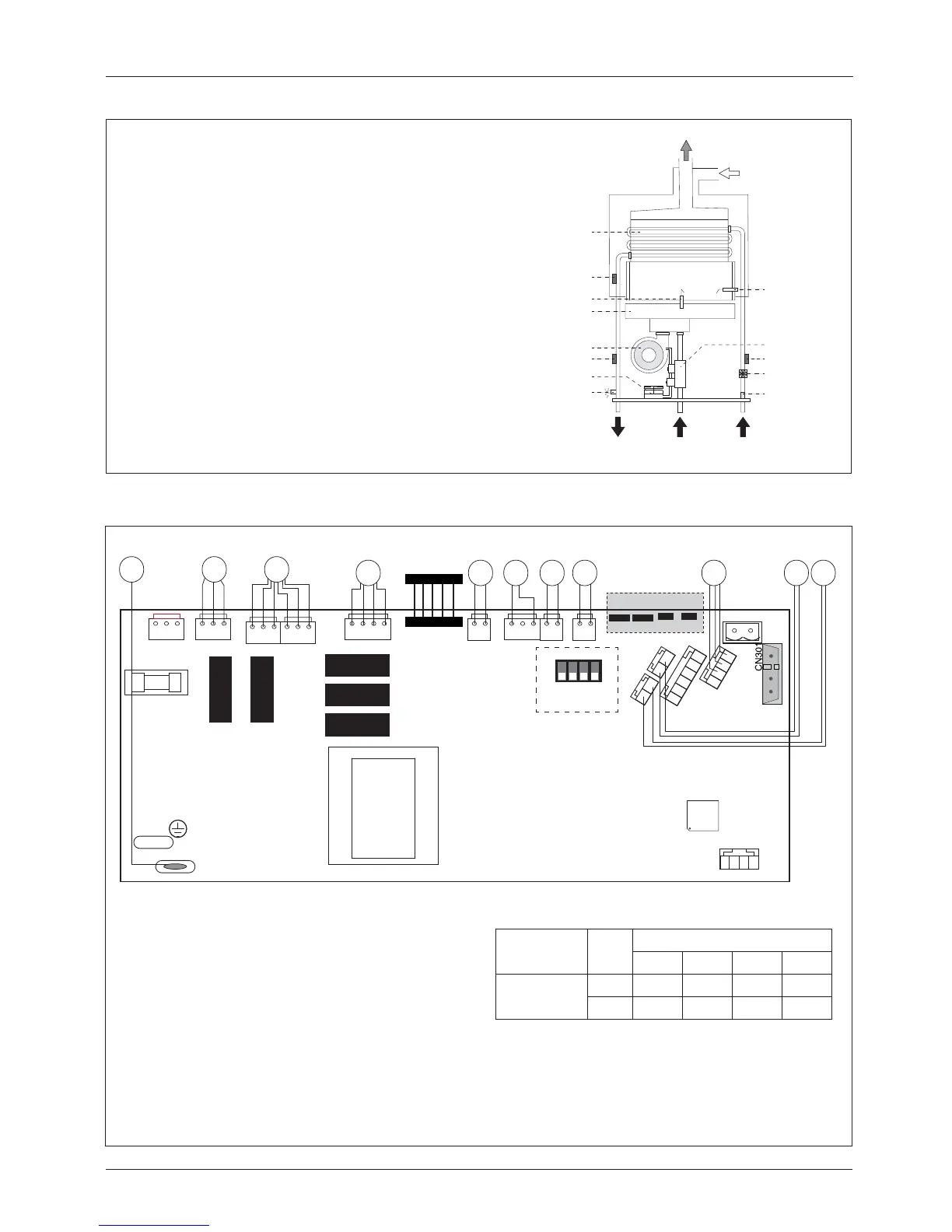
3.4. Operating Principle
3.5. Electrical Circuit Diagram
CN1
CN2
CN3
CN4
CN6
CN16
P1
P2
SW2 SW3
CN12
CN13
CN14
CN8
CN9
CN10
CN11
6 54321
2
1
2
1
4 3 21
FUSE 2AT
FLAME
4321
CN7
1
ON
234
Display
LN
1 2 3
4 5
6 7 8 9
10
11
microswitch
Legend
1. Detection Electrode
3. Gas valve
4. Spark generator
5. Fan
6. Air pressure switch
7. Overheat thermostat
8. Modulator Gas valve
9. Thermal fuse
10. Water fl ow switch
11. Outgoing water temperature sensor
12. Inlet water temperature probe
B
C
D
1
2
3
4
5
6
7
8
9
11
12
13
10
Legend
1. Heat exchanger
2. Overheat thermostat
3. Detection Electrode
4. Burner
5. Fan
6. Outgoing water temperature sensor
7. Air pressure switch
8. Safety valve
9. Cold water inlet fi lter
10. Water fl ow switch
11. Inlet water temperature probe
12. Gas valve
13. Ignition electrode
Microswitch position
Model GAS
Microswitch
1234
NEXT SFT 14
G20
OFF
ON OFF OFF
G31
OFF ON OFF ON
 Loading...