64 / GB
Attention
The electrical connections are made after completing all hydraulic connections
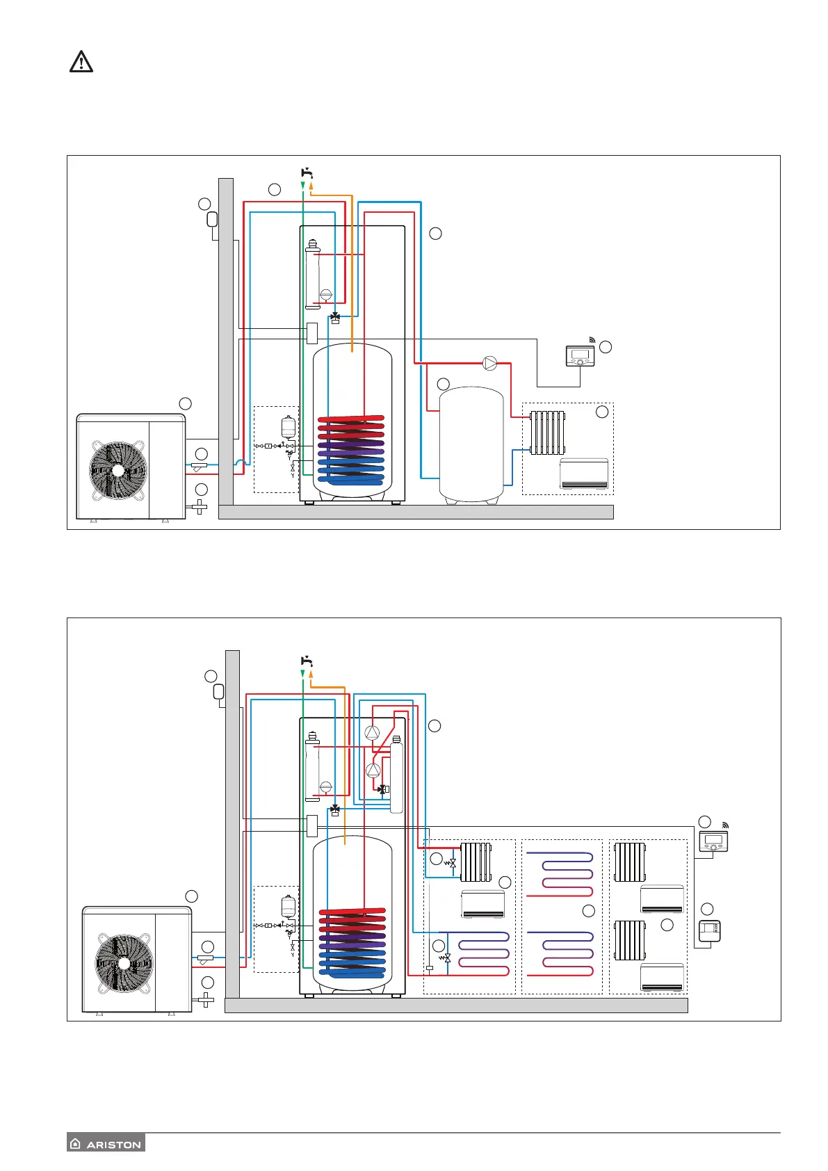
1 ZONE FSP
The circulation pump which drives the fluid between the external unit and the heating/cooling system in positioned in the
external unit. The unit also has two “2 kW” heating elements and an expansion vessel.
2 ZONE FSP
The circulation pump which drives the fluid between the external unit and the heating/cooling system in positioned in the
external unit. The unit also has two “2 kW” heating elements and an expansion vessel, two circulation pumps and a mixer
valve to supply two heating/cooling zones at dierent temperature.
Legend:
1. Internal unit
2. External unit
3. External sensor
4. High-temperature heating zone /
Low temperature cooling zone (with fan coil unit)
5. Buer (optional)
6. System interface Sensys and Sensys Net
7. Filter
8. Cartridge Anti-freeze
Legend:
1. Internal unit
2. External unit
3. External sensor
4. Two high and low temperature heating/cooling zones
5. Two low temperature heating/cooling zones
6. High-temperature heating zone /
Low temperature cooling zone (with fan coil unit)
7. System interface and Sensys Net
8. Zone Control room sensor
9. Filtre
10. Cartridge Anti-freeze
11. By pass
NOTE: Installation with under-floor systems
For under-floor installations, make sure to install a safety device on the heating delivery circuit, as required by DTU 65.11. For the ther-
mostat hookup, refer to “Electrical connections”.
If the delivery temperature is too high, the system stops in both domestic hot water and heating/cooling modes, and the remote control
will report error code 116 “Under-floor heating thermostat open”. The system will start again when the manual re-arm thermostat is
closed.
VE
11
11
1
7
8
4
5
6
2
9
10
3
 Loading...