65 / GB
ATTENTION:
The electrical connections shall be made after completing all hydraulic connections.
ATTENTION:
After Power OFF of the external unit, is needed to wait at least 5 minutes before turn it ON again.
The internal and external units must be powered separately according to what is indicated on the tables. Between the internal and
external units should also be made a EBUS 2 connection. This connection may be made through the use of a cable of reduced section
(recommended section 0,75 mm
2
). Do not let this cable walk along a power connection.
Electrical circuit
• Check that the voltage and frequency of power supply from the network coincide with the data shown in the data plate of the
appliance (see table)
• In order to ensure greater security, the main electrical system should be checked by a qualified technician before proceeding with
the installation (see note).
• It is recommended to verify the presence of surge protection devices (SPD), in compliance with the national regulations in force (IEC
60364 and its national harmonizations), in the power supply line and the presence of residual-current devices and magneto-thermal
switches on the electrical board which powers the external and internal unit separately. However, it is recommended to install an
SPD even if the risk level resulting from CRL calculation is low.
• The electrical system must meet all the legal requirements in force.
• The manufacturer is not liable for any damage caused by installation with improper grounding or abnormalities in the electrical
system.
• Check that the installation is adequate to support the power consumption of the installed units, indicated on the data plate of the
product.
• The electrical connections must be carried out with the aid of a fixed supply connection (do not use mobile sockets) and equipped
with a bipolar switch, having a distance between the contacts of at least 3 mm.
• It is essential to connect the appliance to a correctly grounded electrical circuit, as to ensure the safety of the installation.
• It is also forbidden to use for the grounding of the system and the hydraulic connection of the heating tubes.
• The manufacturer is not liable for any damage caused by installation with improper grounding or implant level anomalies electric.
• Connect the power cord to a 230V-50Hz or (400V-50Hz), verifying the polarizations of the L-N (or L1, L2, L3, N) connection and the
connection to the earth (see table of electrical connections).
• The section of the used cables must comply with the power of the installation (see plate characteristic).
• The section of the power supplier’s cables, showed in a table, must be considered as minimal.
• For the electrical connection of the installation, you shall not use power strips, extension cords and adapters. It is also prohibited to
use the hydraulic pipes and heating system pipes to ground the installation.
The system is not protected against lightning. If you need to change the fuses, use fast fuses.
Warning: Before obtaining access to terminals, all supply circuits must be disconnected.
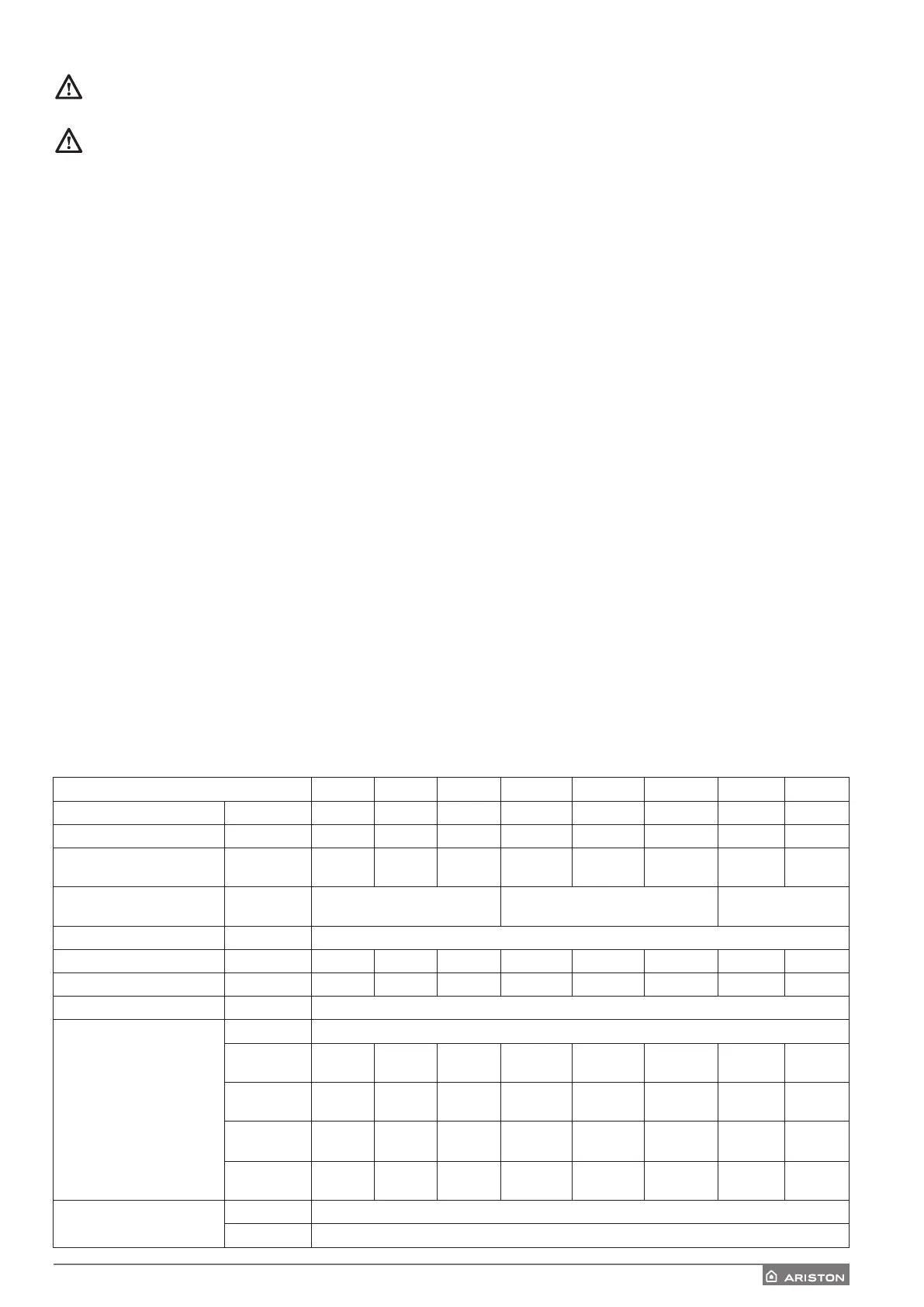
ELECTRICAL WIRING
TABLE OF ELECTRICAL CONNECTIONS
EXTERNAL UNIT
40 M EXT 50 M EXT 70 M EXT 70 M-T EXT 90 M-T EXT 110 M-T EXT 90 M EXT 110 M EXT
Nominal running current / phase A 6.4 8 11 3.8 6 7,3 18 22
Maximum running current / phase A 9 11 16 5.4 8.4 10 23 27
Cutout - Circuit Breaker size A
12-C type
13-C type
16-C type 20-C type 10-C type
12-C type
13-C type
13-C type 32-C type 32-C type
Dierential Circuit Breaker size
(RCCB)
mA 30 - F or B type 30 - B type 30 - F or B type
Starting current A < 3
Nominal Voltage V 230 230 230 400 400 400 230 230
Operating voltage limits V 216-243 216-243 216-243 376-424 376-424 376-424 216-243 216-243
Cos phi > 0,9
Power supply cable
Reference H07RN-F
Min. cables
section
3G2.5 3G4 3G4 5G2.5 5G2.5 5G2.5 3G6 3G6
Max diameter
[mm]
14 16.2 16.2 17 17 17 18 18
Recommended
cables section
3G4 3G4 3G4 5G4 5G4 5G4 3G6 3G6
Max diameter
[mm]
16.2 16.2 16.2 19.9 19.9 19.9 18 18
Communication cable
Reference H05RN-F
Cables section 2 x 0.75 mm
2
 Loading...