EN: Installation Sheet
Description
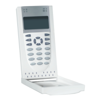
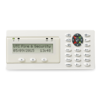
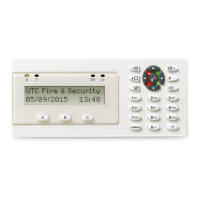
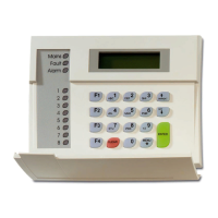
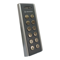
ATS1125 Keypad is a remote arming station (RAS) with built-in
Mifare card reader for Axon x700 control panels.
The keypad bracket fits the most common 60-mm junction wall
boxes, such as U40 or 502E.
Caution: Read this manual before any operations with the
equipment, especially before installation and first power up.
Mounting the keypad
WARNING: Electrocution hazard. To avoid personal injury or
death from electrocution, remove all sources of power and
allow stored energy to discharge before installing or removing
equipment.
Cautions
• Due to safety reasons it is not allowed to install the
product in any location outside the building where the
corresponding control panel is placed (unless a proper
RS485 line insulation module is used). Network to network
insulation is required as no proper separation might
interact with alarm system signal integrity and cause
unexpected results.
• Any overhead lines are prohibited.
• Due to safety reasons it is not allowed to wall-mount the
device higher that 2 meters from the floor, and in reach of
children.
• It is prohibited to perform any installation operations by
non-instructed person, in EN 62386 meaning.
Two lock screws hold the mounting bracket at the rear (see
Figure 4). Remove the mounting bracket before installation. To
do so, unscrew the lock screws, then slide the mounting
bracket down and pull its bottom away from the body of the
keypad.
Hinged cover
To mount the hinged keypad cover, follow the steps indicated
in Figure 6.
A Cut out the removable elements on the bottom of the
housing.
B Insert the cover into the provided hinges.
C Slide the hinges with the cover into the housing slots.
To install the keypad:
1. Mark the hole positions on the mounting surface using the
mounting bracket, and drill the holes.
Caution: Ensure that the keypad is installed on a flat
surface to prevent interference with the tamper switch.
2. Attach the bracket to mounting surface using provided
screws, including pry-off tamper screw, which fixes the
pry-off tamper element (Figure 3, item 3).
3. Connect cable to the keypad terminal. See also
“Connections” on page 3.
4. Set the bus termination jumper (see Figure 2, item 2), if
required. Terminate the bus cabling.
WARNING: All power should be turned off to the control
panel before wiring the RAS.
5. Place the keypad onto the bracket, top first, and gently
snap in place. Tighten the locking screws at the bracket
until the keypad is firm. Do not overtighten.