Do you have a question about the Aritech ATS1135 and is the answer not in the manual?
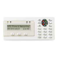
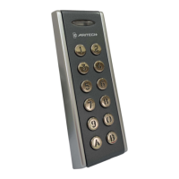
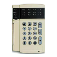
Overview of the ATS1135 Keypad as a remote arming station with built-in card reader.
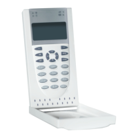
Details on how to mount the ATS1135 keypad unit, including reference to mounting points.
Guidance on connecting the ATS1135 keypad to the control panel for installation.
Information regarding the rear tamper switch and its sealing for system functionality.
Configuration of RAS address and bus termination using DIP switches on the rear.
Detailed information on power supply and data bus connections for the RAS keypad.
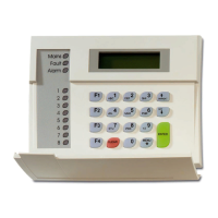
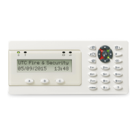
Explanation of the Power, Fault, and Alarm LEDs on the keypad.
Details on keypad and LCD backlight, contrast, and buzzer settings adjustable via the menu.
Describes the system behavior upon initial power up, including buzzer confirmation.
Guidance for diagnosing general faults like no LED indication or system fault messages.
Explains the function of RX and TX LEDs for diagnosing communication faults.
Overview of keypad programming options accessible through the installer menu.
| Model | ATS1135 |
|---|---|
| Brand | Aritech |
| Keys | 16 |
| Backlight | Yes |
| Power Supply | 12 VDC |
| Type | Keypad |
| Display | LCD |
| Communication | RS485 |
| Tamper protection | Yes |
| Humidity | 95% non-condensing |