Do you have a question about the Aritech ATS1125 and is the answer not in the manual?
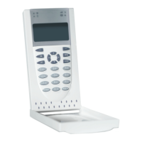
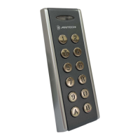
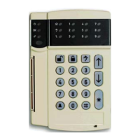
ATS1125 Keypad is a remote arming station (RAS) with built-in Mifare card reader for Axon x700 control panels.
The keypad bracket fits most common 60-mm junction wall boxes, such as U40 or 502E.
To mount the hinged keypad cover, follow the steps indicated in Figure 6.
WARNING: Electrocution hazard. Remove all power sources before installing or removing equipment.
The tamper switch must be inactive (closed) for the system to work correctly.
To terminate the bus, insert the termination jumper if needed. Max two switches per bus.
Keypad connects via RS485 data bus, up to 1.5 km. Use two-pair twisted, shielded data cable.
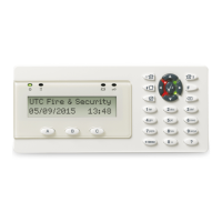
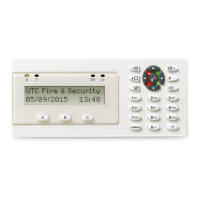
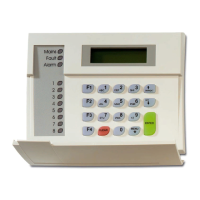
Provides status on Power, System Status (Red/Orange), and Fault (Yellow).
Adjust LCD brightness, backlight, and buzzer volume by pressing multiple buttons.
Configurable key backlight and dim nightlight settings are available.
Device communicates via encrypted connection, locking it to the panel for security.
Access local installer menu via tamper switch to set options like language and addresses.
Set the keypad bus address. Changing address resets the secure channel key.
Options to reset SC key, load default logo, or reset all keypad settings.
Addresses secure communication failures and system fault indications.
Details supply voltage, operating current, RF power, dimensions, and environmental ratings.
Use RoHS compliant materials and processes when printing logos on the keypad.
Details certifications (CE, EN 50131) and compliance with EU directives.
Intended for qualified professionals; warranty disclaimers and product safety information.
Provides website links for product information, documentation, and support.
The ATS1125 Keypad is a remote arming station (RAS) equipped with a built-in Mifare card reader, designed for use with Axon x700 control panels. It is intended for professional installation and operation.
The keypad serves as a primary interface for the alarm system, allowing users to arm and disarm the system, view system status, and interact with various system functions. The integrated Mifare card reader enables convenient card-based access control, enhancing security and ease of use.
The keypad bracket is designed to fit common 60-mm junction wall boxes, such as U40 or 502E. Installation involves marking and drilling holes on the mounting surface, attaching the bracket with provided screws (including a pry-off tamper screw), connecting the necessary cables, and setting the bus termination jumper if required. The keypad then snaps onto the bracket and is secured with locking screws.
A hinged cover can be mounted by cutting out removable elements on the housing, inserting the cover into hinges, and sliding the hinges with the cover into the housing slots.
The keypad requires power from the bus (+12V, 0V) from the control panel. If the distance to the control panel exceeds 100m, an auxiliary power supply or DGP AUX PWR can be used. Data communication occurs via the RS485 data bus (D+/D-), which supports distances up to 1.5 km from the control panel. It is recommended to use two-pair twisted, shielded data cable (WCAT 52/54), with the shield connected to system ground at one end only.
An "IN" terminal allows connection of a normally open, momentary push-button switch for a request-to-exit function. An "OUT" terminal provides an open collector output, programmable via the control panel.
The keypad includes a tamper switch that must be closed (inactive) for the system to operate correctly. This switch is closed when the keypad is mounted on its bracket. If the tamper switch is active (open), the LCD display will show "RAS Tamper."
The bus can be terminated by inserting the termination jumper (Figure 2, item 2). A maximum of two termination switches or links set to "On" is allowed per bus. Refer to the control panel installation guide for detailed instructions on bus termination.
The keypad features several LED indicators:
Simultaneous button presses allow adjustment of keypad settings:
Default settings include key backlight (bright) for approximately 240 seconds after a key press, and nightlight (dim). These settings can be customized through the keypad menu.
The device communicates with the control panel via an encrypted connection. Once a secure connection is established, the device becomes locked to that specific system, ensuring it only works via the secure channel and with that panel. This prevents unauthorized communication modes and enhances protection against cyberattacks. If the device is reconnected to a different system or an equivalent device is replaced, it will not function. Removing the device from the panel configuration makes it impossible to reconnect it to the same system. To unlock the device for use in any system, the secure channel key must be reset, or the device address changed.
The ATS1125 provides a local installer menu for setting various options. To access this menu, power up the keypad with the tamper switch open, then press "Menu" when the welcome screen appears. If the keypad address is not set, the menu opens automatically after the welcome screen.
Navigation within the menu uses:
If secure communication fails (e.g., LCD keypad shows "System Fault" and cannot be polled by the control panel), it indicates a misalignment of secure keys between the two devices. This requires a reset on one or both devices.
Regular cleaning of the keypad surface is recommended to ensure optimal performance and longevity. The device does not require specific user-level maintenance beyond keeping it free from dust and debris. Any internal maintenance or repair should only be performed by qualified professionals.
| supply voltage | 8.7 to 15.1 VDC; 12.0 VDC nom. |
|---|---|
| maximum operating current at 12.0 VDC | 115 mA |
| maximum operating current at 13.7 VDC | 110 mA |
| normal operating current at 12.0 VDC | 25 mA |
| normal operating current at 13.7 VDC | 22 mA |
| input (IN terminal) max. appearing voltage | 13.9 VDC |
|---|---|
| open collector output (OUT terminal) | 13.7 V max. at 50 mA max. |
| wireless operating frequency | Mifare 13.560 ±0.007 MHz |
| dimensions | 97 x 155 x 25 mm |
|---|---|
| weight | 230 g |
| operating temperature | −10 to +55°C |