Tamper switch
The tamper switch must be inactive (closed) for the system to
work correctly. The tamper switch is closed by mounting the
keypad onto the mounting bracket. In operation, the LCD
display will show “RAS Tamper” when active (open).
Data bus termination
To terminate the bus, insert the termination jumper (Figure 2,
item 2), if needed. There must be no more than two termination
switches or links set to On for any bus. Refer to the control
panel installation guide for details about the use of termination
switches or links.
Connections
See Figure 7.
• +12 V, 0 V: The keypad can be powered using the bus “+”
and “−” power from the control panel, if the distance
between the keypad and the control panel does not
exceed 100 m. Otherwise the keypad can be powered by
AUX PWR from a DGP, or by an auxiliary power supply.
See “Specifications” on page 4 for the required power
supply specifications.
• D+/D−: D+ is the data positive connection and D− is the
data negative connection of the data bus.
The keypad is connected to the ATS panel via the RS485
data bus, up to 1.5 km from the control panel. It is
recommended to use two-pair twisted, shielded data cable
(WCAT 52/54). D+/D− should be connected by one
twisted wire pair. The shield of any bus cable must be
connected to system ground at one end only. The keypad
does not provide an earth connection for this purpose. If
the bus is daisy-chained to the keypad, ensure that the
shield of the cable is jointed to provide continuity of data
cable shield. Isolate the wires and the shield of the cable
correctly to prevent any short circuit on the keypad.
• IN: A request to exit button (normally open, momentary
push-button switch) can be connected across “IN” and
“0V” terminals. When pressed, this button controls the
request to exit function.
• OUT: Open collector output. For maximum allowed
current, see “Specifications” on page 4. Refer to the
control panel programming manual for details.
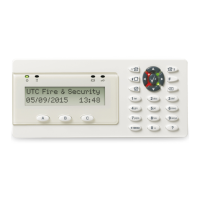
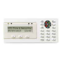
LED indications
Figure 5
(1) Power. Green: The Power LED is on when the control panel is
powered by the AC supply.
(2) Status:
Red On: Areas set
Red flashing: Alarm condition active
Orange On: Part set
Orange flashing: System fault active / General alert (EN 50131)
Green On: System is ready to set
Green flashing: Entry / exit time active
Blue flash: Valid card presented / Access granted
Off: Not ready to set / Armed display active
(3) Fault. Yellow: The Fault LED illuminates to indicate detection of
a system fault.
Operating features
Keypad shortcuts
Use keypad shortcuts to adjust the following keypad settings
(press these buttons simultaneously).
• LCD brightness: Menu
+ Up or Down
• Keypad backlight brightness: F + Up or Down
• Keypad nightlight brightness: F + Left or Right
• Buzzer volume: Cancel
+ Up or Down
Note: In certain cases, the buzzer cannot be muted, as this is
not allowed for compliance reasons.
Key backlight and nightlight
The default key backlight and nightlight settings are as follows:
• Key backlight on (bright) for approximately 240 s following
a key press.
• Nightlight on (dim).
These functions can be changed from the keypad menu.
Secure channel
This device can communicate with the panel using an
encrypted connection. When the secure connection to a control
panel is established, the device will be locked in this system,
so that it will work only via secure channel and only with this
panel. Any other communication modes will be disabled.
This device will not work if you reconnect it to another system,
replacing an equivalent device.
Removing the device from the panel configuration will make
impossible reconnecting this device to this system.
This functionality protects the system against cyberattacks.
To unlock the device and use it in any system, reset the secure
channel key or change the device address. See “Programming
options” below for more details.
Programming options
ATS1125 provides a local installer menu, through which certain
options can be set.
The installer menu is accessible when powering the keypad up
with the keypad tamper switch open. To enter the menu, press
Menu
when the welcome screen is shown.
Note that the menu opens automatically after the welcome
screen if the keypad address is not set.
Use the following buttons to navigate the keypad menu:
• Up or Down: Select a parameter
• Left or Right: Change the parameter value
• Enter
: Confirm the parameter change
• Cancel
: Exit menu
See Programming Map in Figure 8.
Language
Change the Installer menu language.
 Loading...