page 14 / 75 0MNA080A55-GB REV 01
- table of connections-
100kVA 120kVA 160kVA 200kVA 250kVA
Power line
Imax (*) [A] 145 173 229 288 359
External fuse type gG [A] 160 200 250 315 400
BYPASS (**)
Current [A] 145 173 231 289 361
External fuse type gG [A] 160 200 250 315 400
OUTPUT
Current [A] 145 173 231 289 361
BATTERY
Permanent battery eq. Current [A] 200 240 320 400 495
(*)100% load, minimum input voltage, battery charging; (**) inside the UPS, no max. current protection device is provided on
the by-pass line, this protection must be provided in the system;
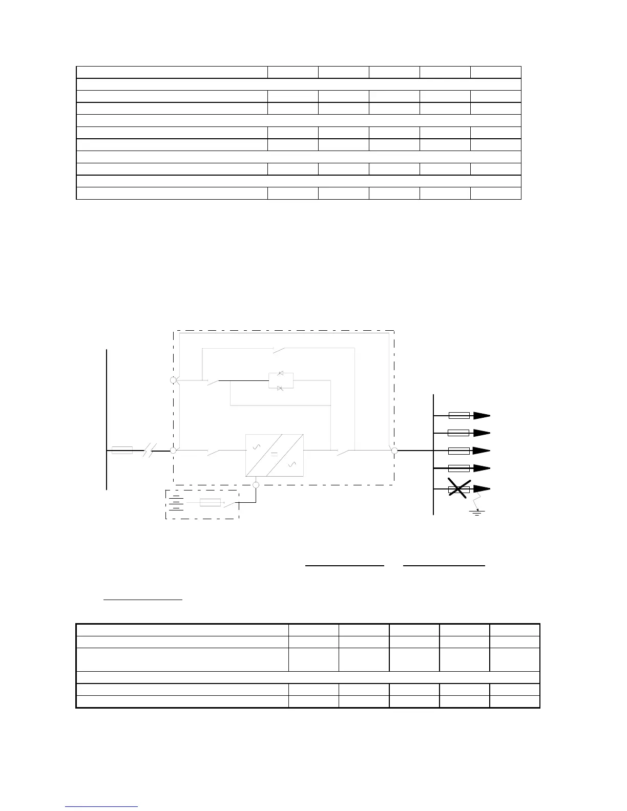
3.1.2 Selectivity
The system where the UPS is inserted must be set up in such a way that in the event of a shortcircuit on one of the
lines downstream of the UPS, the fuse on the output will be triggered rather than the fuse located at the UPS input.
This is known as selectivity, and ensures that the remaining feeders maintain the power supply.
In order to select the correct protection devices to be inserted downstream of the SENTRY MPS-HP, the following
two operating modes have to be taken into consideration: mains power supply
and battery power supply.
With mains power supply
the output fuse must be selective with the input fuse; the condition is verified for the
following values:
100kVA 120kVA 160kVA 200kVA 250kVA
rated output current: [A] 145 173 231 289 361
type gG fuse used at the UPS input
(as shown in the table of connections) [A]
160 200 250 315 400
maximum fuse at the UPS output for selectivity:
fuse size for type gG fuse [A] 100 125 160 200 250
fuse size for type aM fuse [A] 63 80 125 125 160
At least two feeders are necessary in order to use the UPS at rated load with fuses of type gG.
UPS
F
H