page 24 / 75 0MNA080A55-GB REV 01
3.3.8 MULTI I / O (optional)
-L- The function of this accessory is to convert external signals from the SENTRY MPS-HP (e.g. temperature of
environment, temperature of battery premises, etc.) into signals by means of relay contacts or via serial output
RS485 in MODBUS protocol.
It has the following characteristics:
- 8 inputs (e.g. humidity, smoke, etc. sensors)
- communication with the UPS via serial port
- 8 relays configurable with 8 events on the SENTRY MPS-HP
- RS232 output port with configurable messages
- RS 485 output port MDBUS /JUBUS with configurable messages.
3.3.9 Battery temperature sensor (optional)
-M- The UPS has a connector for connection of the kit, which consists of a sensor to be placed inside the battery
cabinet. The use of the temperature sensor allows the UPS control logic to regulate the values of the charge and
maintenance voltage according to the working temperature of the battery.
3.3.10 Dual Bus System – UGS (optional)
-N- Two independent systems may be configured with Dual Bus with a single source or a separate source.
The synchronization option (UGS) keeps the outputs of the two systems always synchronized, regardless of the
input variations and when the system is running from the battery. Each system may be made up of a maximum of 4
parallel-connected UPSs. This system has been designed for configurations using STSs (Static Transfer Switches)
since this guarantees switching from one uninterruptible source to another without affecting the loads.
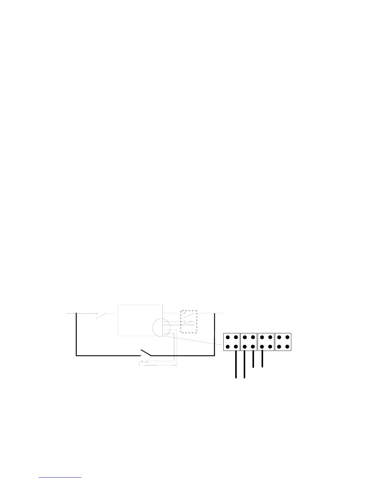
3.3.11 SWOUT and SWMB aux.
-P, Q- Terminals to be used for the connection of the auxiliary contacts of switches inserted in the SENTRY MPS-
HP system, see also the section on “Insertion of additional system sectioning devices” on page 37.
Inserting additional disconnectors to supplement those already in the UPS means that the whole equipment can be
replaced without interrupting the power supply to the load.
Additional output disconnector S2, additional disconnector S of the external maintenance by-pass.
The auxiliary contacts S2 and S must be connected to terminals P and Q.
For safe removal, place the UPS onto by-pass, close S, open S1 and S2 and disconnect the UPS.
Contact S2 must be in the same position as the switch while S must be in the opposite position (auxiliary open with
switch closed, vice versa with switch open)
UPS
S2
aux
S1
LOAD
MAINS
aux
da S
da S2
S