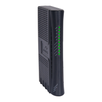
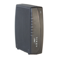
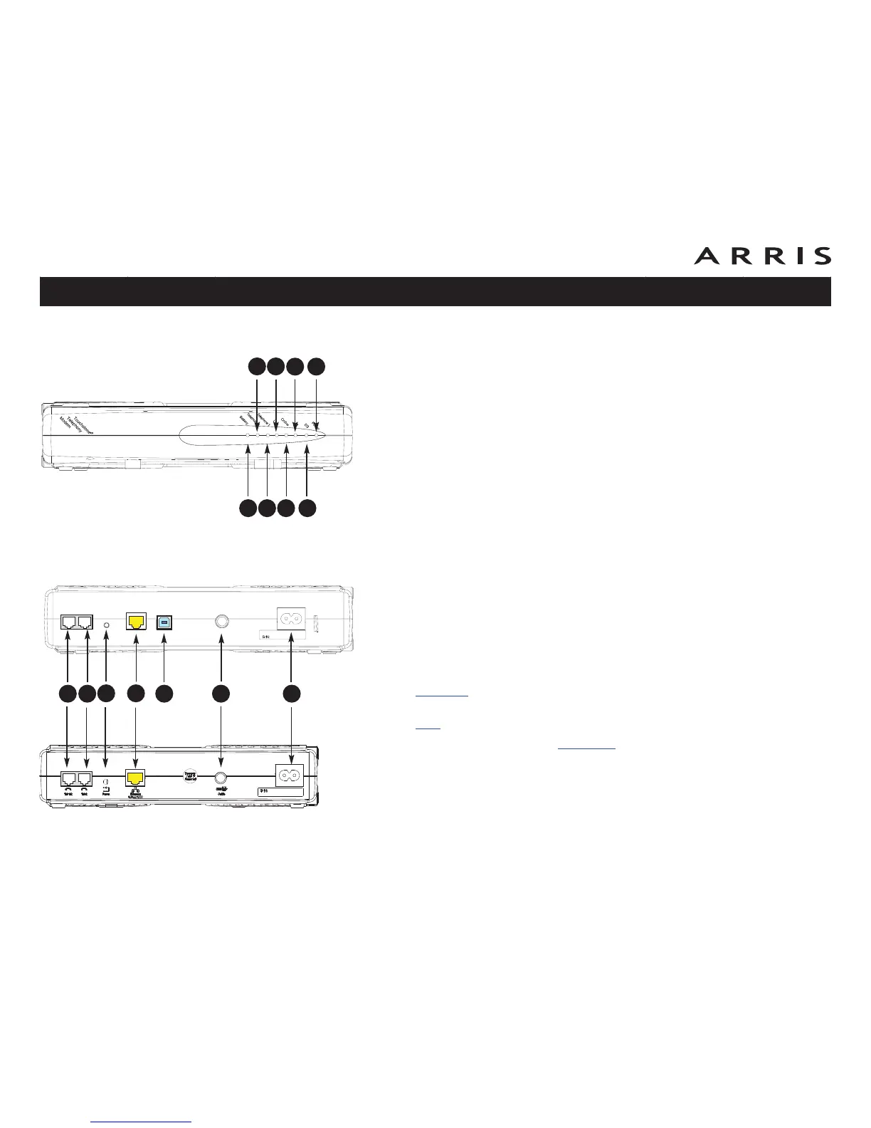
Front Panel
The front of the Telephony Modem provides the following indicators.
A Battery (TM702G only): indicates battery status
B Telephone 2: indicates status of line 2
C Telephone 1: indicates status of line 1
D Link: indicates Ethernet or USB (if equipped) connectivity between the Tele-
phony Modem and computer
E Online: indicates internet data transmission status
F US: indicates upstream connectivity
G DS: indicates downstream connectivity
H Power: indicates whether AC power is available to the unit
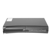
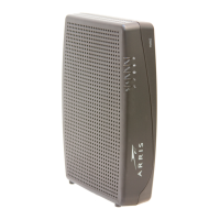
Rear Panel
The rear of the Telephony Modem has the following connectors and controls:
A Tel 1/2 (grey): connector for the first phone line (or both lines of a 2-line
phone).
B Tel 2 (grey): connector for the second phone line.
C Reset button: resets the Telephony Modem as if you power cycled the unit.
Use a pointed non-metallic object to press this button.
D Ethernet
connector (yellow): for use with a computer or home network LAN
connection.
E USB
connector (blue, if equipped): for use with a computer USB connection.
F Cable: connector for the coax cable.
G Power: connector for the power cord.
Touchstone TM702 Telephony Modem User’s Guide
Safety
Getting
Started
Battery
Installation Installation
USB
Drivers
Ethernet
Configuration Usage Troubleshooting Glossary
19
A
B
C
D
E
F
G
H
A
C
B
D
FE G
TM702G
TM702A/B