Console cable pinouts
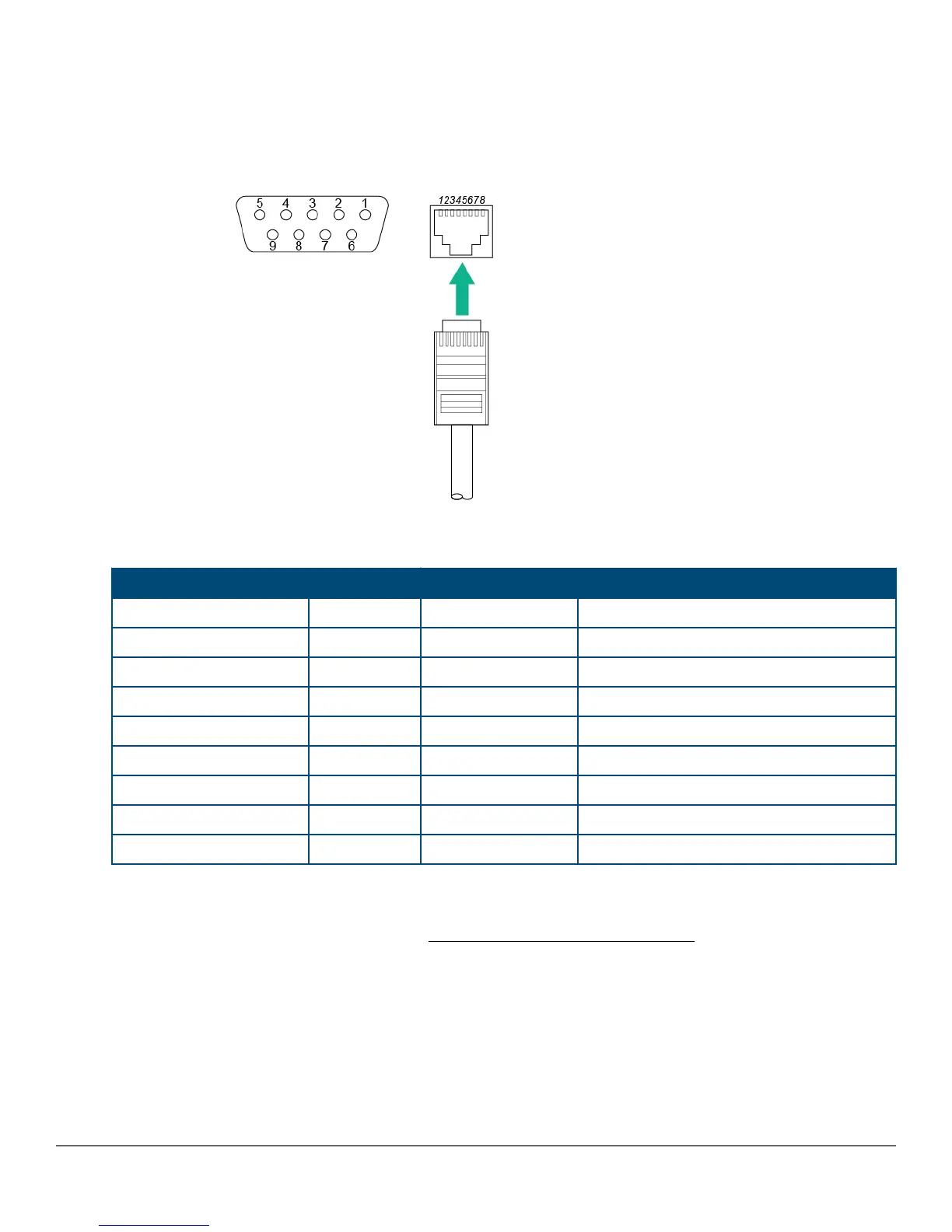
The console cable has an RJ-45 plug on one end and a DB-9 female connector on the other end. The figure
below displays the mapping of the RJ-45 to DB-9 pins.
Figure 22: RJ-45 to DB-9 pinouts
Table 10: Mapping of RJ-45 to DB-9
RJ-45 (Signal reference from chassis) DB-9 (Signal reference from PC)
Reserved 1 8 CTS
Reserved 2 6 DSR
TXD 3 2 RXD
Reserved 4 1 DCD
GND 5 5 GND
RXD 6 3 TXD
Reserved 7 4 DTR
Reserved 8 7 RTS
9 RI
Connect the network cables
Connect the network cables, described under Cabling and technology information on page 64, from the
network devices or your patch panels to the fixed RJ-45 ports on the switch or to any SFPs you have installed in
the switch.
Using the RJ-45 connectors
To connect, push the RJ-45 plug into the RJ-45 jack until the tab on the plug clicks into place. When power is on
for the switch and for the connected device, the port LED should light to confirm a powered-on device (for
example, an end node) is at the other end of the cable. If the port LED does not come on when the network cable
40 Aruba 2930F Switch Series Installation and Getting Started
Guide



 To Next Page