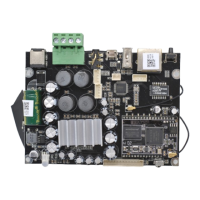
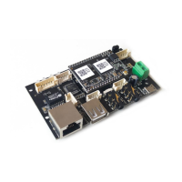
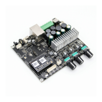
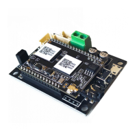
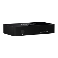
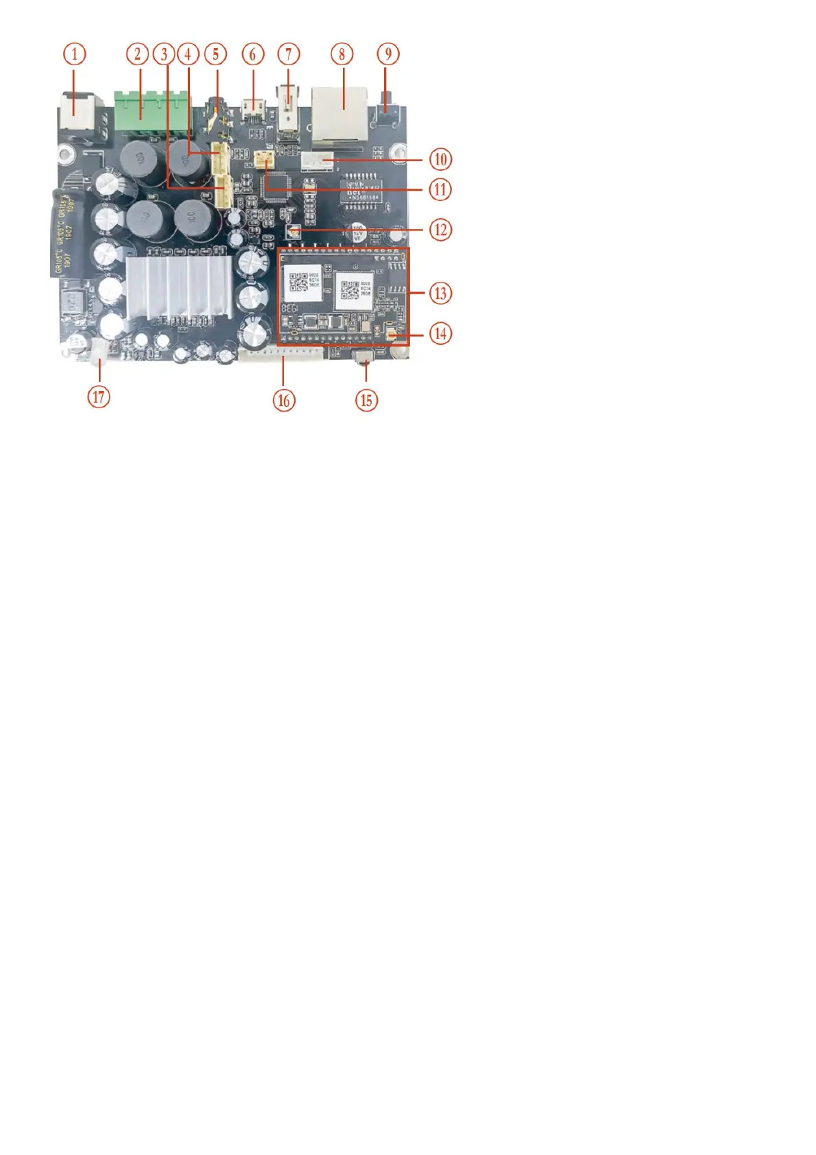
1 DC-IN 10 GPIO2,GPIO1,GND,VCC
2
Speaker-Out
(R+,R-,L+,L-)
11 GND,SPDIF2
3 GND,MIC2,MIC1,GND(reserved) 12 Bluetooth Antenna
4 RIN,GND,GND,LIN 13 WiFi Module
5 Line-in 14 WiFi Antenna
6 Mirco USB 15 IR
7 USB 16 IIC,ADC_KEY,LED,RESET,TX,RX,GND,VCC
8 Ethernet RJ45 17 LED
9 Power Button
*(9) Power Button: Short press to power off and on; When in WiFi mode, long press (press and hold the button for more than 5 seconds) to reset
WiFi settings and enter the paring mode; When in Bluetooth mode, long press to terminate the current connection.
Further Notes
(16) PH2.0-13P: IIC_SDA, IIC_SCL, IR, ADC_KEY, LED_BLUE, LED_RED, LED_WHITE, LED_GREEN, RESET, TX, RX, GND, VCC3V3
IIC_SDA, IIC_SCL: This is reserved for the display panel.
IR is used to extending the IR receiver.
KEY is used for external buttons, refer to the circuit right for key The LED pins are used to extend the LED and are common-anode connected.
You should connect 3.3V to a current limit resistor and then to LED and then to the pin.
TX/RX is UART interfaces to send events and receive controls.
(11) PH2.0-2P: GND, SPDIF2: This is reserved for external SPDIF input.
(4) PH2.0-4P: R_IN, GND, GND, L_IN: For analog input to up2stream amp board, it has the same signal as the 3.5mm Aux jack.
(3) PH2.0-4P: GND, MIC2, MIC1, GND: This is reserved for future use.