TD 92989EN
15 October 2014 / Ver. B
Installation Guide
IP-DECT Base Station & IP-DECT Gateway
23
3.2.6 Secure the Cable
For safety reasons secure the base station cable to
a convenient point at about 30 cm from
the base station.
If for some reason the base station drops, it is secured by the cable.
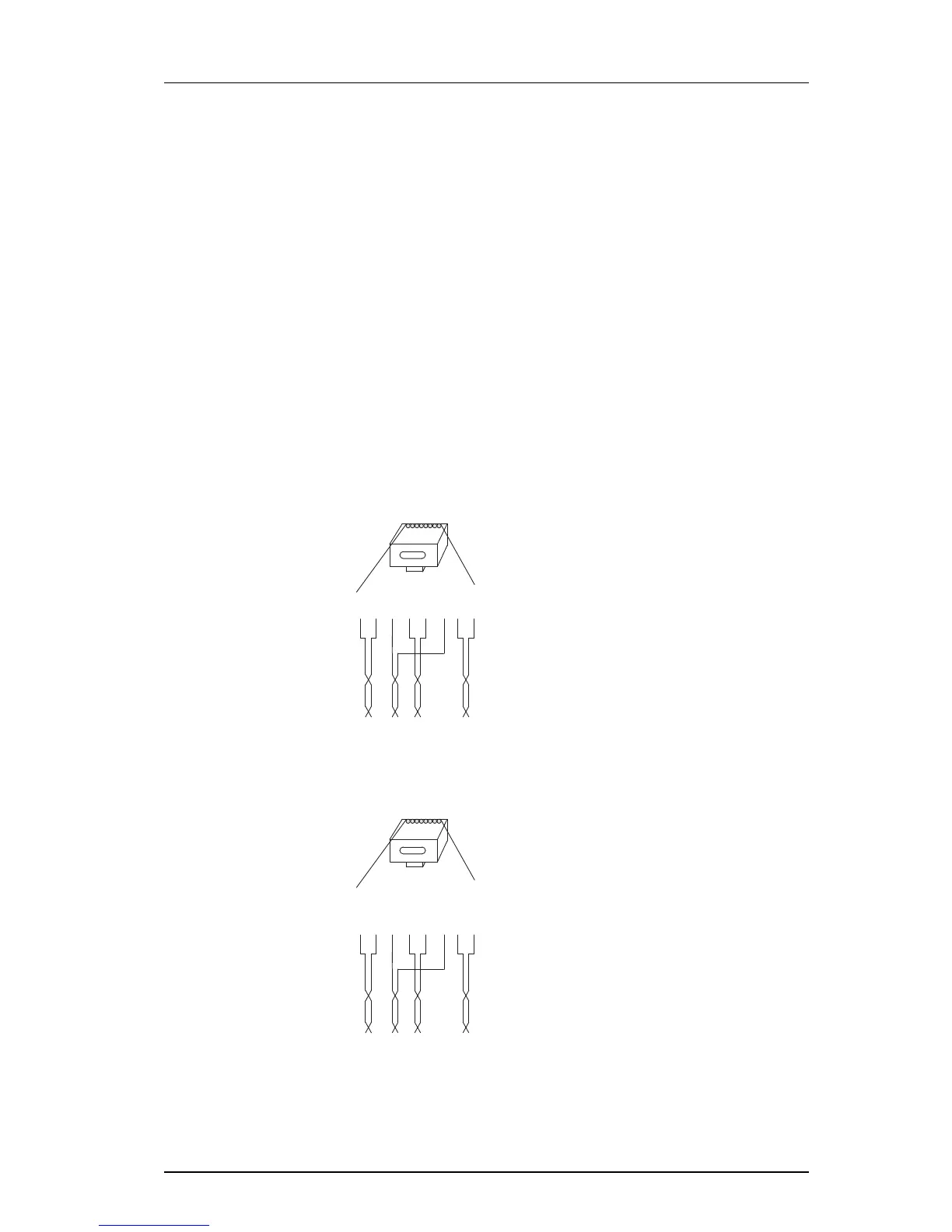
3.2.7 Pinning
1 Cut the cable to the correct length and conne
ct the cable to a RJ45 modular jack.
2 For information on the pinning of the data jack see the following:
• IPBS, Pin the IPBS Cable on page 23.
• BS3x0 and DB1, Pin the BS3x0/DB1 Cable on page 24.
Do no
t plug the connector in the base station yet!
NOTE: Since the distance between the ba
se station and the wall is limited, a RJ45 modular
jack without cable retention must be used.
Pin the IPBS Cable