TD 91684GB
16 April 2015 / Ver. G
Installation Guide
T942C and T942C/2 Central Unit
13
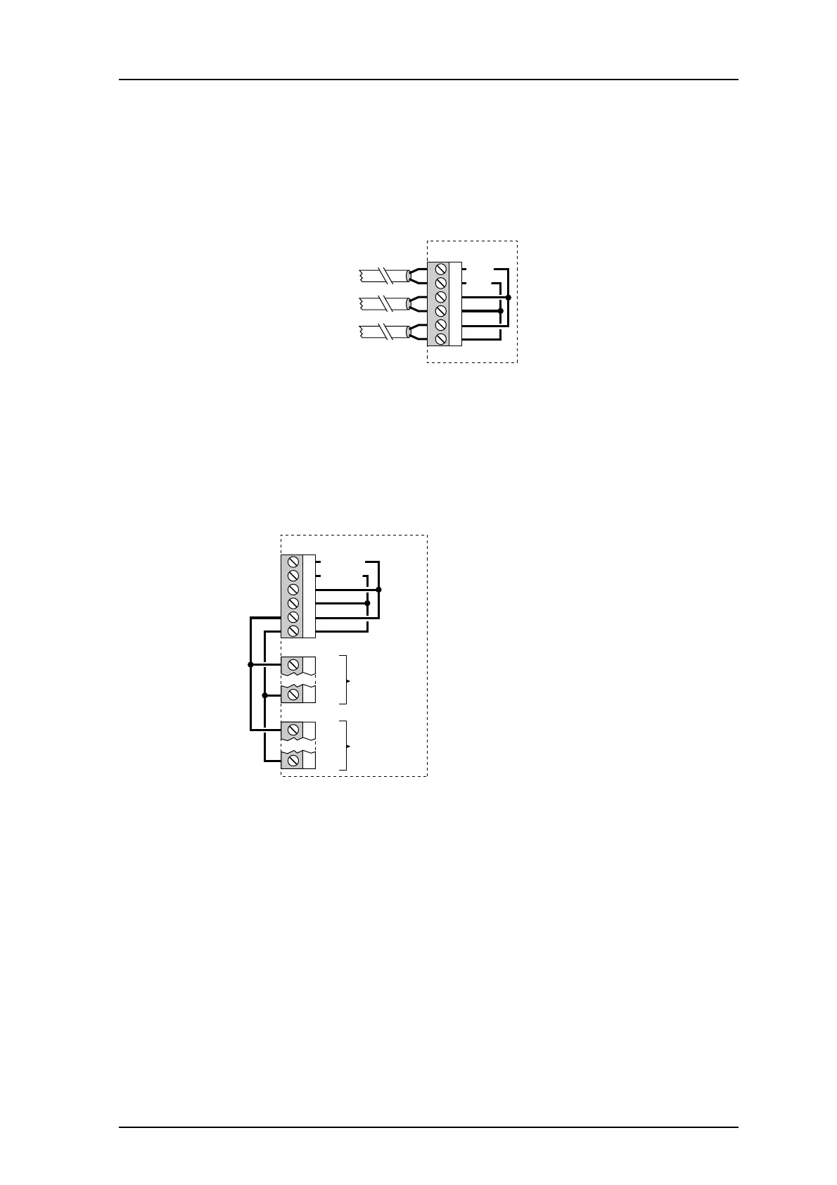
1.4.7 Connection of Supply Voltage
1 Add the FP5 Fuse board 1.25A, a very-fast actin
g (FF) fuse, to the circuit board, in
between connector J03 and the screw terminal.
2 Connect the supply voltage to connector J03 screw 1 and 2.
See the System Insta
llation document, chapter Power Supply.
J03
4
5
6
3
1 +12V
2 GND
Supply voltage in
Supply voltage out
to other units
Supply voltage out to
digital inputs/outputs
Figure 14. Connector J03
NOTE: If the digital inputs and outputs are to be used
they must be provided with supply
voltage.
3 Supply the digital inputs and outputs with
voltage via connections between J03 and
J11/J12 (see drawing below).
J11
J03
4
5
6
3
1 +12V in
2 GND in
6 GND
1 +12V
J12
6 GND
1 +12V
to external
digital outputs
to external
digital inputs
Figure 15. Connection of digital inputs or outputs.
If galvanic isolation is required, remove the connecti
ons between J03 J11/J12, and
connect a separate power supply to J11/J12.