TD 91684GB
16 April 2015 / Ver. G
Installation Guide
T942C and T942C/2 Central Unit
14
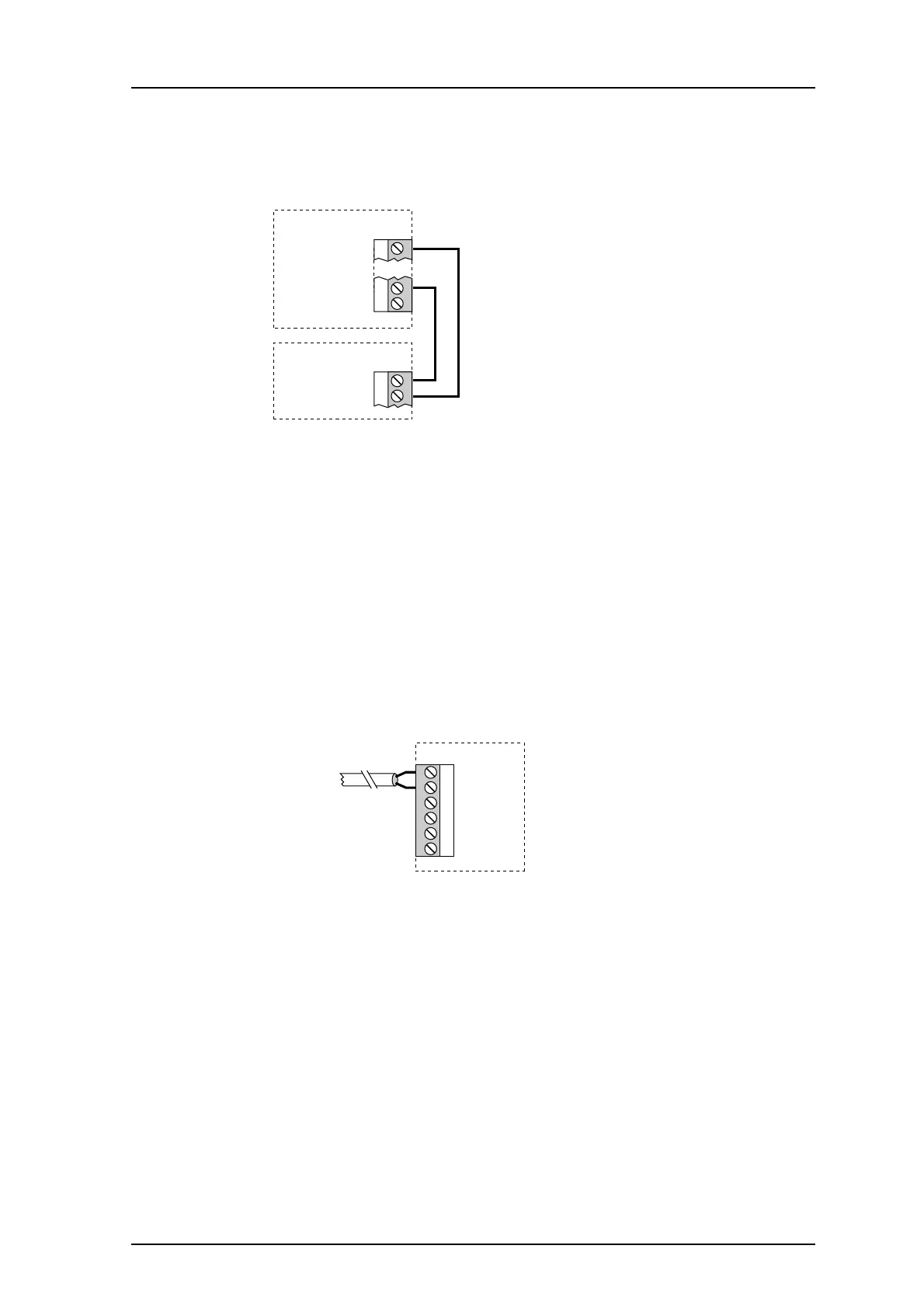
1.4.8 Connection of Reference Module in a FL-System (used only in paging systems)
Connect a t
wisted-pair from connector J12 screw 6 and 2 to Reference Module T938RM
connector J04 screw 5 and 6, respectively (polarized!).
J04
J12
T942C
T938RM
GND 5
REF ON 6
GND 6
1
OUT1 (CODE1) 2
Figure 16. Connection of the Reference Module to the Central Unit.
NOTE: The digital outputs must be provided with supply voltage, see 1.4.7 Connection of
Supply Voltage on page 13.
1.4.9 Connection of Monitor Input
In some cases it may be desirable to prevent the
H/U952T Terminal Transmitters from
transmitting, e.g. when a carrier wave is already in the air.
Monitor input can be used to prevent the Central Unit
both from activating the output stage
in the transmitters and from sending the transmitter code to them when a carrier wave is in
the air.
Connect a twisted-pair from the m
onitor source to the Central Unit (connector J11, screws 1
and 2).
J11
4
5
6
3
1 +12V EXT IN
2 IN1
to monitor
Figure 17. Monitor connection.
NOTE: The digital inputs must be provided with supply voltage, see 1.4.7 Connection of
Supply Voltage on page 13.