TD 91684GB
16 April 2015 / Ver. G
Installation Guide
T942C and T942C/2 Central Unit
12
1.4.6 Connection of Buses
Buses are connected either via modular bus cabling or twiste
d-pairs.
NOTE: The data buses are polarized. Use only twisted-pa
irs for two-wire connections!
Bus connection via Modular Bus Cabling
See figure 12 on page
12 for information about modular bus connectors.
1 Connect modular bus cabling to J01 and J02.
2 Connect additional modular bus cabling:
J14: connect only the C-bus to another Central Unit via a quick-connect terminal block
(type Krone)
Pin 1
234567
Pin 8
Pin
1
2
3
4
5
6
7
8
Signal
Not used
Not used
Not used
Not used
Not used
Not used
A1 data bus
A2 data bus
J08
Pin
1
2
3
4
5
6
7
8
Signal
C1 data bus
C2 data bus
DR1 data bus
DR2 data bus
D1 data bus
D2 data bus
Aux relay 1
Aux relay 2
J14
Pin
1
2
3
4
5
6
7
8
Signal
A1
A2
B1
B2
D1
D2
Not used
Not used
J01 + J02
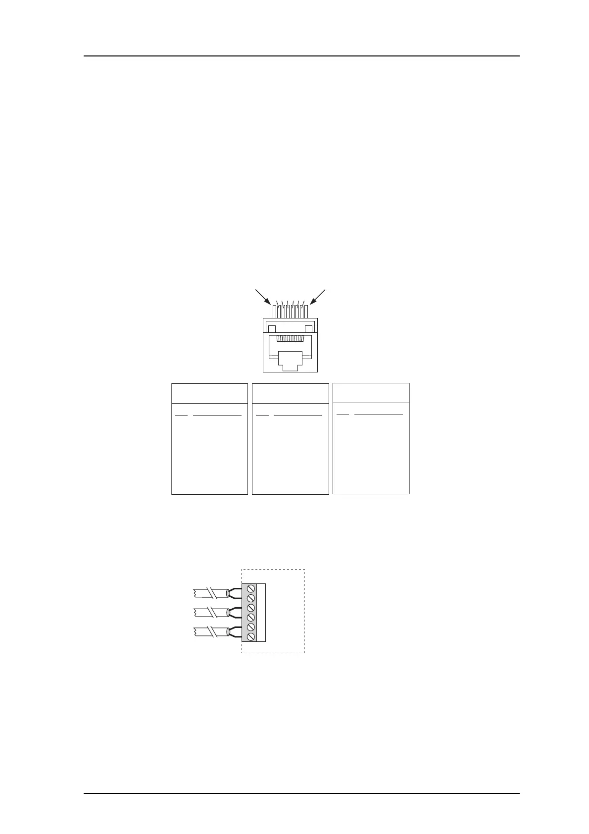
Figure 12. Modular connectors J01, J02, J08 and J14.
Bus connection via twisted-pairs
J04
4
5
6
3
1
2
A-bus
D-bus
C-bus
Figure 13. Twisted-pairs connection.
• A-bus to J04 screw 3 and 4.
• C-bus to J04 screw 1 and 2.