8
COM
IL1
IL2
IL3
Serial
communication
(optional)
Remote set input
wire
transmitter
Input
measurement
X
X
mA
Volt
J, L,
K, S…
A
B
B
Pt100
(1)
8
3
2
Retransmission
output
(option)
7
TX
RX
i
4…20 mA
+ 24 Vdc (2)
Y4
Logic
inputs
4
Y2
Y1
Y1F
Auxiliary
outputs
Single power supply
100...240 Vac - 50/60 Hz
A Relay
A Relay
2
nd
channel (cool)
Continuous mA, V
Logic 0/18 Vdc
Y3
Y1
Main
output
1
6
5
2
3
4
5
6
7
9
10
21
22
23
24
25
26
27
28
29
12
13
14
15
16
17
18
19
20
111
!
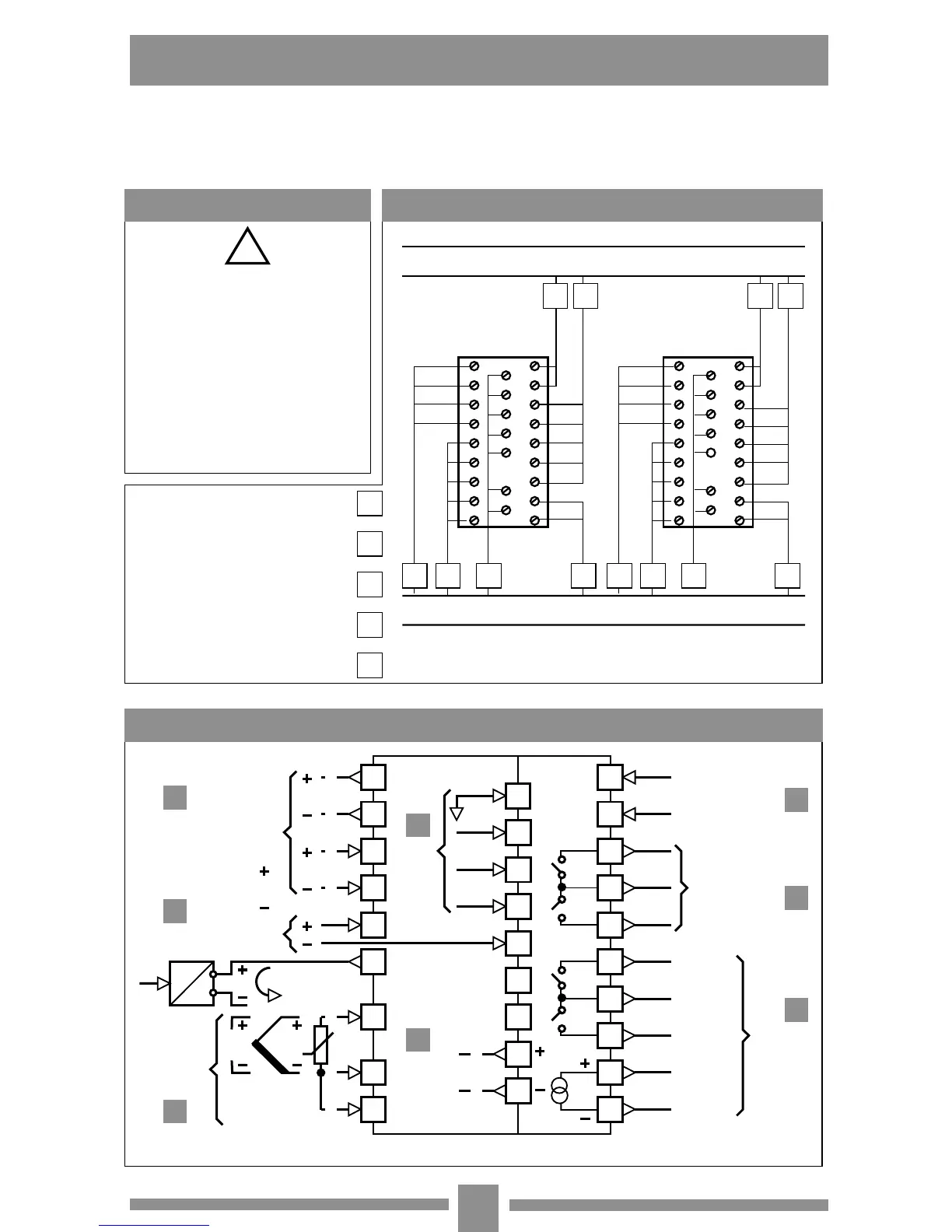
Single out supply line from
power line
Keep away from teleruptors,
electromagnetic contactors and
powerful motors
Keep away from power groups,
in particular if with phase control
Channel for low level signal conductors
Power supply and output channels
A
B C
D E
A B C
D E
Serial communication
Analogic inputs
Logic inputs and analogic
signals
Input
Outputs
B
C
D
E
A E E
Although this controller is designed to resist the heaviest disturbances
present in industrial environments (level IV of standard (IEC 801-4), it is
advised to keep to the following precautions:
Wiring diagram
Precautions Advised conductor course
(-)
(-)
(+)
4 • ELECTRICAL WIRING

 Loading...


