ASD Document 600541 Rev. G 23 TerraSpec® User Manual
www.asdi.com Chapter 4 Fiber Optic Interface
In order to achieve the best response from ASD instruments it may be
necessary to adjust the fiber optic interface between the external fiber optic
cable (shown in Figure 4-2 and Figure 4-3) and the instrument connection.
Note: The fiber optic bundle matcher has a standard 1.7 mm fiber optic bundle
input.
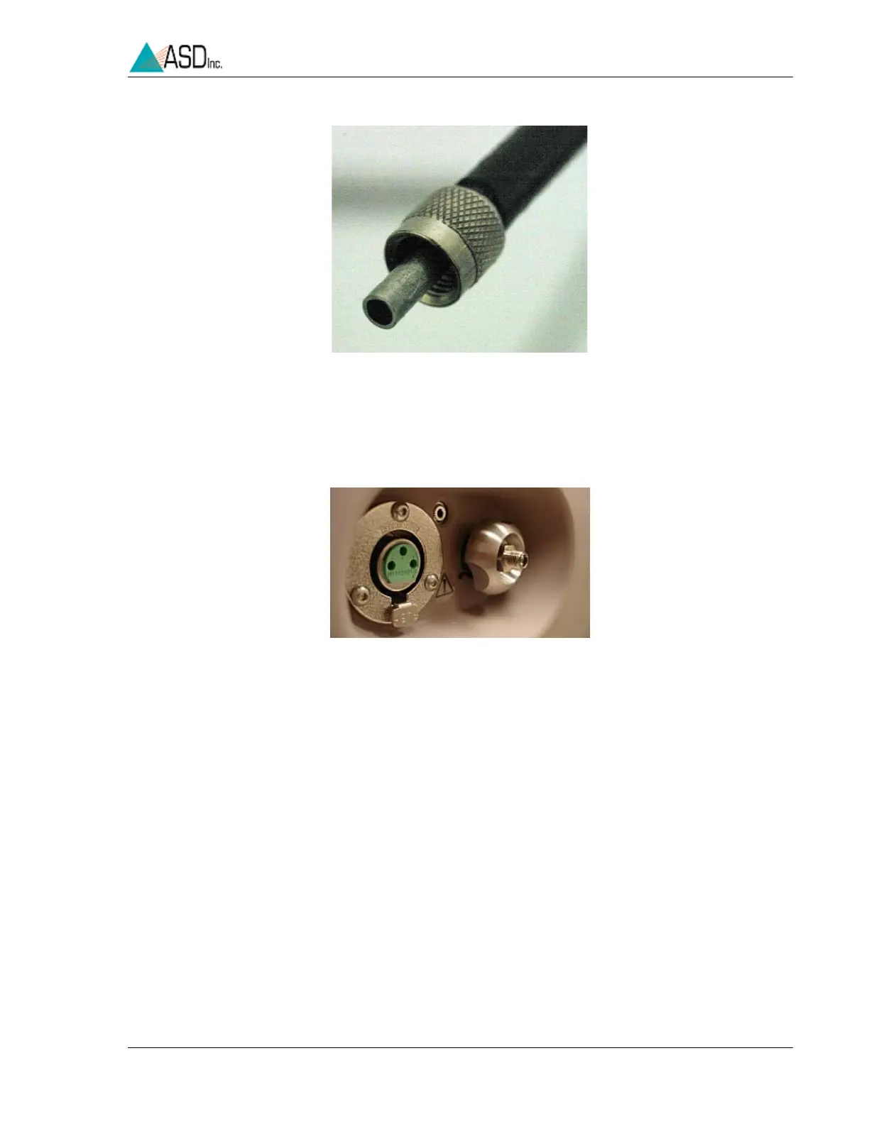
Figure 4-1 Connector for the fiberoptic cable.
Figure 4-2 View of the fiberoptic bundle matcher and the fiberoptic port.