ASD Document 600541 Rev. G 29 TerraSpec® User Manual
www.asdi.com Chapter 4 Fiber Optic Interface
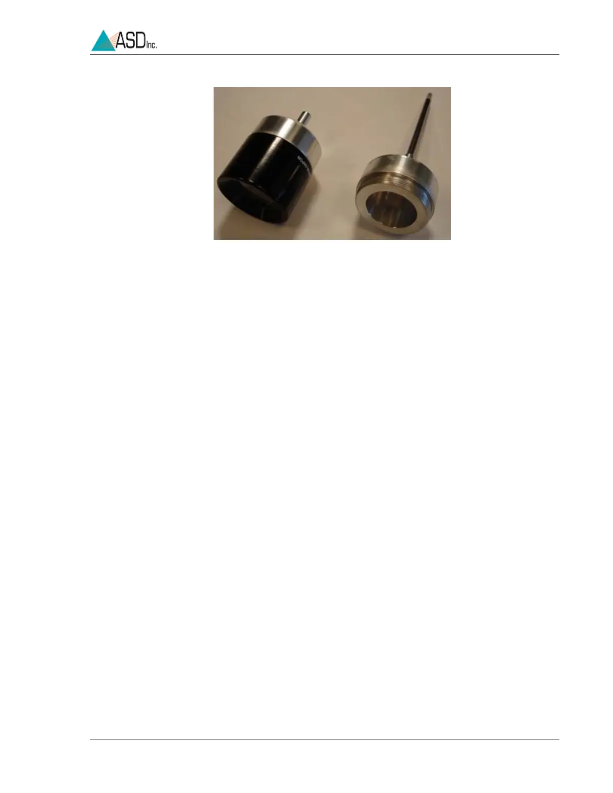
2 Attach the magnifier to one end of the fiber optic cable.
3 Point the other end of the fiber optic cable close to a light.
4 Observe which fibers transmit light.
Details about the Fiber Optic Cable and LEDs
• The LEDs will only turn on for the ranges installed in the spectrometer.
Selecting one that the spectrometer does not have will not cause a
problem.
• Each range has a different LED color so that you can see the fibers in the
cable that are associated with it: RED for VNIR; WHITE for SWIR1;
GREEN for SWIR2.
• The fiber bundle of the internal cable contains 19 fibers for the VNIR, and
9 for each SWIR region.
• The fiber bundle of the external cable contains 44 fibers.
• Each broken internal fiber results in an approximate 5% loss of response
in that particular range (VNIR, SWIR1, or SWIR2). Each broken external
fiber results in a few percentage loss of response over the entire range. It
is hard to quantify how a broken fiber in the external cable affects the
response of any given range, each time the external cable is connected to
the spectrometer, the alignment with the fibers of the internal cable will
most likely be different.
The instrument can be successfully used with a few broken fibers in each
range, although with a reduction in signal strength.
For severely damaged internal fiber optic cables, send the instrument back to
ASD Inc. in its carrying case for repairs. For severely damaged external fiber
optic cables, order replacements from ASD Inc.
Figure 4-10 Short and Long Magnifier Assemblies