Setting up the F100
F100-14-001.2 Page 3-3
ASL 2005
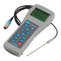
3.4 F100 thermometer inputs
There are two input channels; two 5 pin DIN input-sock ets are located at the rear of the instrument.
These are designed to take either PRT or thermistor probes. Channel A is colour-coded red. Channel
B is colour-coded blue.
Figure 3.4 - Rear panel
Either channel can accept either Smart or Passive probes; any combination of probes can be us e
together. Smart probes (described in section 6.0) contain their own calibration information and
communicate this to the F100 as soon as they are used. Passive probes do not contain calibration
information and the F100 must be set-up with the calibration information for eac h probe us ed (and
each time the probe is changed).
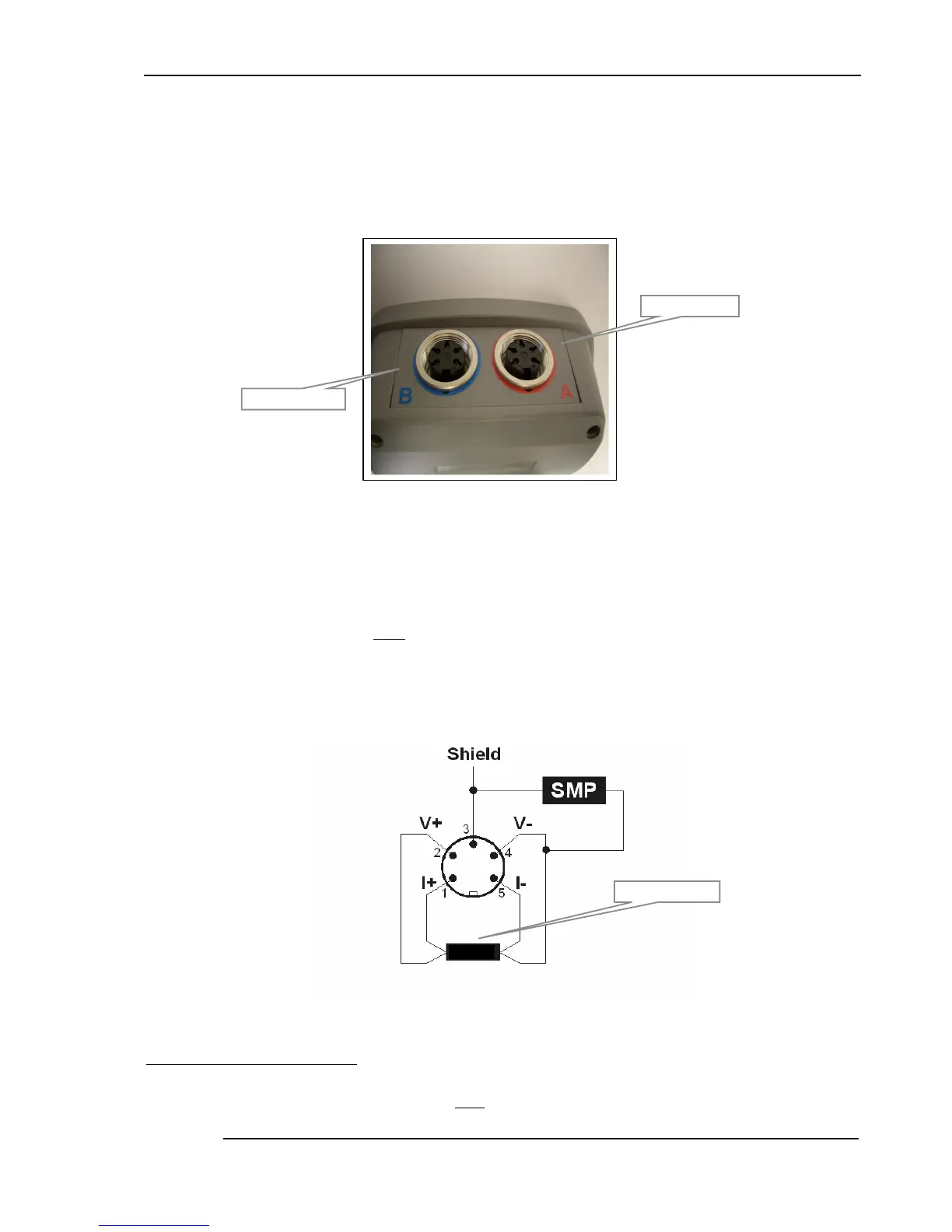
Probe connection information for both PRTs and thermistors
4
is shown below (viewed looking towards
the sockets) -
Figure 3.4.1 4-Wire SMART probe PRT/thermistor input
4
Two wire PRTs/thermistors must have the probe pins1 & 2 connected together and also pins 4 & 5 connected together.
Channel B (blue)
Channel A (red)
PRT or thermist or