VAR8 and Variants - Product Description
Issue: 02 complete, approved
Page 19 of 54
FIRE
SYSTEM
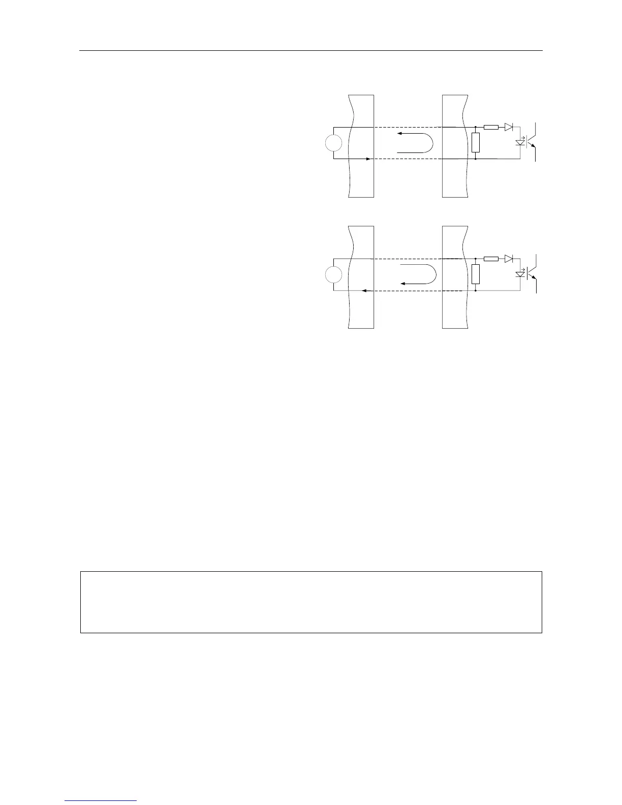
Cabling to Fire System
+V
-V
I
ROUTER
CONTACT INPUT
I
OPTO OFF
MONITORING
FIRE
SYSTEM
Cabling to Fire System
I
ROUTER
CONTACT INPUT
OPTO ON
ACTIVE
+V
-V
+
-
+
-
END OF LINE
RESISTOR (*)
I
END OF LINE
RESISTOR (*)
(*) ONLY CONTACT INPUTS ON THE VAR8
BASE UNIT CAN HAVE INTERNALLY
FITTED END OF LINE RESISTOR
Fire Alarm Sounder Interface
The opto-isolated inputs may be used as a reverse
polarity sounder circuit interface to a Fire Alarm
system. In this DVA triggering method the link
between the fire panel and the VA system is
monitored at the Fire Panel by means of End of
Line Resistors in the VAR8. This is the current
recommendation of BS5839. The Fire panel
monitors the current flowing in the End of Line
Resistor. Reversing the polarity activates the input.
VAR8 base unit contacts 1 to 10 can have
internally fitted End of Line Resistors. However the
VAR8 does not have End of Line Resistors fitted
as standard, as the value required varies
according to the Fire Alarm system. The desired
value for a particular job must be specified with the
order. ASL can then factory-fit the appropriate
resistors. Alternatively these resistors may be fitted
local to the VAR8 during installation. Note that in
this method the final connection into the VAR8 is
not monitored. Note that contact inputs on the
EXP8 Interface Expansion Board cannot have
internally fitted End of Line Resistors.
2.6.1.2 Contact Functions
2.6.1.2.1 Routing: Latching
Any contact may be configured to trigger a latched Latent Route. A momentary, or prolonged, activation of a
latching trigger initiates routing. A separate contact is required for latching inputs, to act as a ‘reset’ contact.
This method is normally used to trigger emergency DVAs from fire systems, although any input source may
be routed in this way. For Fire Alarm DVA messages, BS5839 Pt. 8 recommends the use of latched triggers
with separate resets, so that the message will continue to run even if the trigger pair fails.
Each latching trigger can be configured to initiate routing of any DVA to any output. It is possible to initiate
simultaneous routing of multiple DVAs to multiple outputs with a single trigger. This is so that, for example,
ALERT and EVACUATE messages may be able to be broadcast to different zones for a single trigger. The
DVA or DVAs will play until a momentary assertion of the matching ‘reset’ line, unless the corresponding
trigger is still asserted, in which case the DVA will not be reset.
L
It is possible to configure whether or not a particular route causes busy indications to be shown
on microphone consoles.
For example, a busy indication would not be desired if the Latent Route mechanism was to be
used for enabling a background music source.
If used as a DVA trigger, the contact is configurable for two modes:
• DVA Full
In the ‘DVA Full’ mode, when the ‘reset’ is received, the DVA or DVAs will complete its full message
cycle and broadcast till the end of the DVA message before ending.
• DVA Part
In the ‘DVA Part’ mode, when the ‘reset’ is received, the DVA or DVAs will end immediately even if part
way through a DVA message broadcast.