VAR8 and Variants - Product Description
Issue: 02 complete, approved
Page 23 of 54
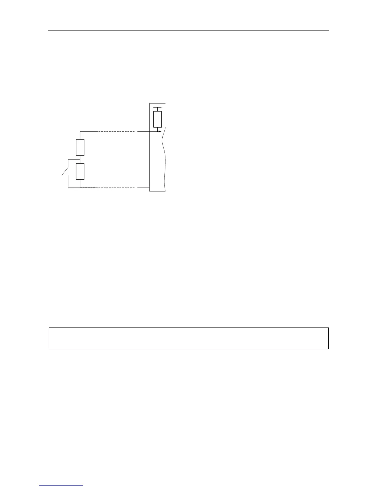
Monitored Analogue Contact
A resistance of 7270 ohms indicates inactive
(switch open) and resistance of 470 ohms
indicates active (switch closed). Open and short
circuit cable conditions are thus readily detected by
resistance values outside this range.
This interface enables the Router to monitor the
interface to the Fire Panel or other contact closure.
The contacts must be fitted with 6k8/470R
resistors. This method of monitoring has been
used extensively in the past and is prevalent in
continental Europe.
Each of the contacts may be independently
assigned as a Routing Control, Routing Reset or
Fault Input. Operation is as described in Sections
“2.6.1.2.1 Routing: Latching”, “2.6.1.2.2 Routing:
Non-Latching, Latent Routes”, and “2.6.1.2.3
External Faults”.
Monitored
Contact
ANALOGUE
INPUT
470 ohms
6k8 ohms
Cabling to Contact
+5 V
4k7 ohms
0 V
ANLG IN1 - 12
2.6.3.3.1 Programme Selector Operation
The application of the Programme Selector function is to allow remote selection of alternative sources to a
specific zone or zones. Normally the programme selector will be mounted within the zone and allow selection
of alternative sources, such as different background music sources.
It is possible to assign a particular Programme Selector to be associated with one, or any group of, Router
outputs. It is then possible to assign which input each position of the Programme Selector corresponds to.
The connection between the Remote I/O Unit and the Programme Selector is monitored, so that open and
short conditions on the cabling are detected and logged by the Router. The Router fault report identifies the
specific Remote I/O Unit and the particular analogue channel number affected.
In the event of such a fault, the routing defaults to that set up on position ‘1’. Normally this would correspond
to all routes being ‘off’.
The same default operation occurs in the event of RS485 communications failure to the Remote I/O Unit.
L
There should be only one Programme Selector associated with an output or group of outputs.
Associating an output with more than one Program Selector would cause unpredictable results.
2.6.3.3.2 Volume Control Operation
The application of the Volume Control function is to allow remote control of the volume of specific input
sources within a specific zone or zones. Normally the volume control will be mounted within the zone and
allow the control of the specific sources, such as background music sources, while leaving the volume of all
other sources unaffected.
It is possible to assign a particular Volume Control to be associated with one, or any group of, Router
outputs. It is then possible to assign which input, or group of inputs, are controlled.
Each step of the volume control gives exactly 3 dB attenuation, with position ‘1’ being ‘off’.
The connection between the Remote I/O Unit and the Volume Control is monitored, so that open and short
conditions on the cabling are detected and logged by the Router. The Router fault report identifies the
specific Remote I/O Unit and the particular analogue channel number affected.