VAR8 and Variants - Product Description
Issue: 02 complete, approved
Page 41 of 54
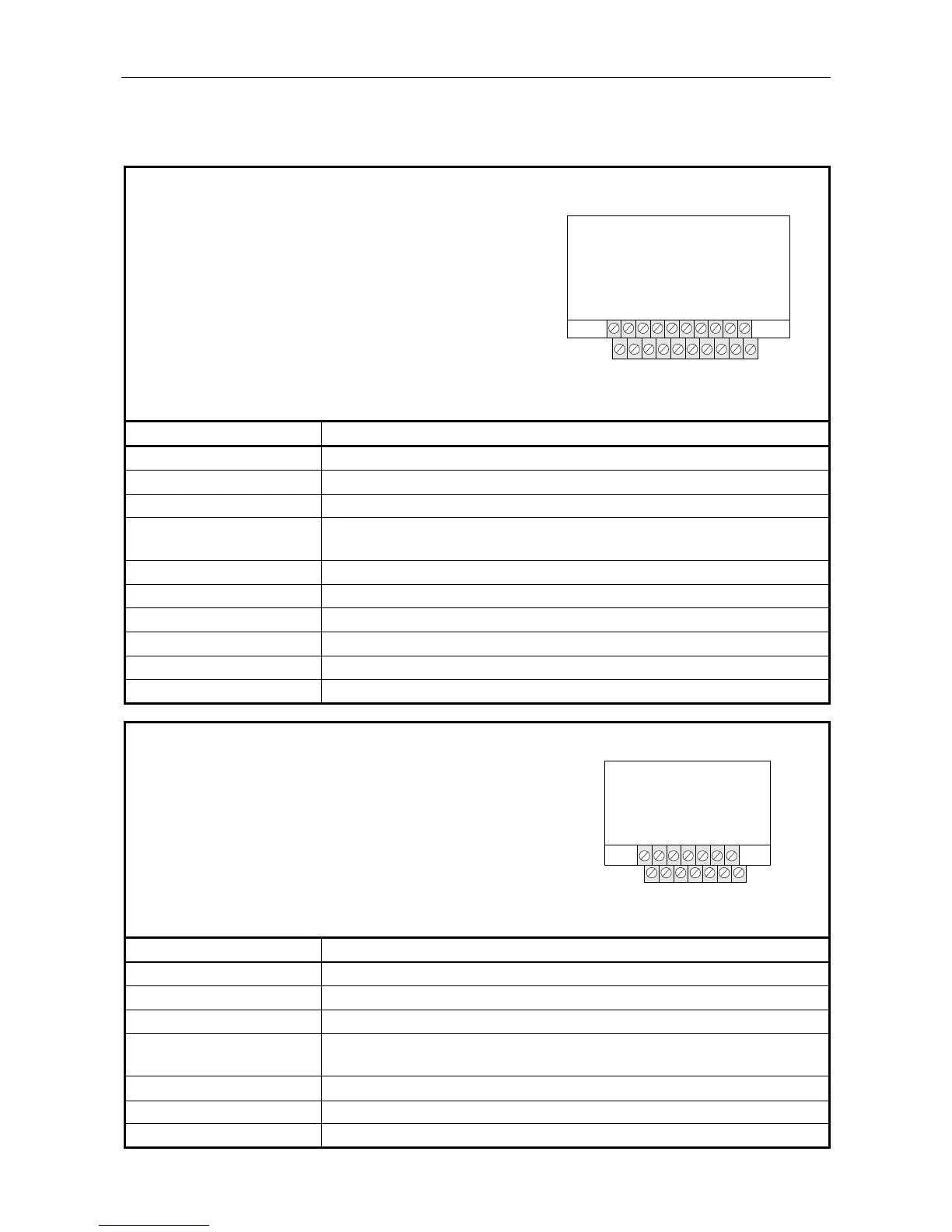
8.2 Audio Inputs
Inputs 1 and 2
• 2x10 way double stack terminal block (5 mm).
• Lower terminal block: Input 1.
• Upper terminal block: Input 2.
• Software configurable inputs with a hardware failsafe mode
for emergency operation in the event of processor failure
(BS5839 requirement).
• Can be used for Fire Microphone, Zoned Fire Microphone,
Paging Microphone, Single Button Microphone, or
Miscellaneous Input.
L Input 1 is not available when the VAR8 is networked.
Network Channel 1 – Input 1
VAR8
DXN
DXP
ACO
SN
PTT-
0V
V+
IN-
IN+
PTT+
DXN
DXP
ACO
SN
PTT-
0V
V+
IN-
IN+
PTT+
Signal Description
DXP Microphone Data+ (EIA RS485 19200 baud)
DXN
Microphone Data− (EIA RS485 19200 baud)
0V 0 V supply
IN+ Balanced audio input +VE
Level: 0 dBu Max. Sensitivity: −20 dBu Input Impedance: 10 kΩ
IN− As above but −VE connection
V+ +V supply (18-36 V)
PTT− Press To Talk switch input (internally pulled up to +5 V by 4k7 Ω)
PTT+
Press To Talk switch input (internally pulled up to +5 V by 4k7 Ω)
ACO All Call Only LED. Open collector drive, 100 mA max
SN Speak Now LED. Open collector drive, 100 mA max
Inputs 3 to 6
• 2x7 way double stack terminal block (5 mm).
• Lower terminal block: Inputs 3 and 5.
• Upper terminal block: Inputs 4 and 6.
• Can be used for Paging Microphone, Single Button Microphone,
or Miscellaneous Input.
L When the Network Interface Card is fitted and the VAR is
networked, inputs 3 and 4 are used for network operation:
Network Channel 2 – Input 3
Network Channel 3 – Input 4
DXP
DXN
V+NB
V+
0V
IN-
IN+
VAR8
DXP
DXN
V+NB
V+
0V
IN-
IN+
Signal Description
DXP Microphone Data+ (EIA RS485 19200 baud)
DXN
Microphone Data− (EIA RS485 19200 baud)
0V 0 V supply
IN+ Balanced audio input +VE
Level: 0 dBu Max. Sensitivity: −20 dBu Input Impedance: 10 kΩ
IN− As above but −VE connection
V+ +V supply (18-36 V)
V+NB Unused