vii
TABLE OF FIGURES
Figure 1 - Symbol Key (page 1 of 3)................................................................................ 1-6
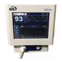
Figure 2- The BIS VISTA Monitoring System.................................................................. 2-2
Figure 3 - Rear Panel ......................................................................................................2-3
Figure 4 - The BISx and PIC ........................................................................................... 2-4
Figure 5 - The BIS VISTA System Block Diagram .......................................................... 3-2
Figure 6 - The BIS VISTA Data Flow Diagram .............................................................. 3-3
Figure 7 - Pole Clamp ..................................................................................................... 4-3
Figure 8 - Schematic of Sensor Simulator Circuit........................................................ 10-2
Figure 9 - Sensor Simulator.......................................................................................... 10-3
Figure 10 - BIS Sensor................................................................................................... 10-3
Figure 11 - Connecting electrodes #2 and #4. .............................................................. 10-4
Figure 12 - Connecting electrode #3 with #4, and #1 with #2. .................................... 10-4
Figure 13 - Safety Tester Contact Points....................................................................... 10-5