SECTION 10 APPENDIX I
_______________________________________________________________________
10-4
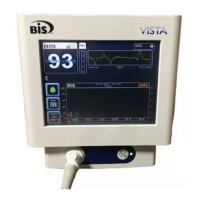
Figure 11 - Connecting electrodes #2 and #4.
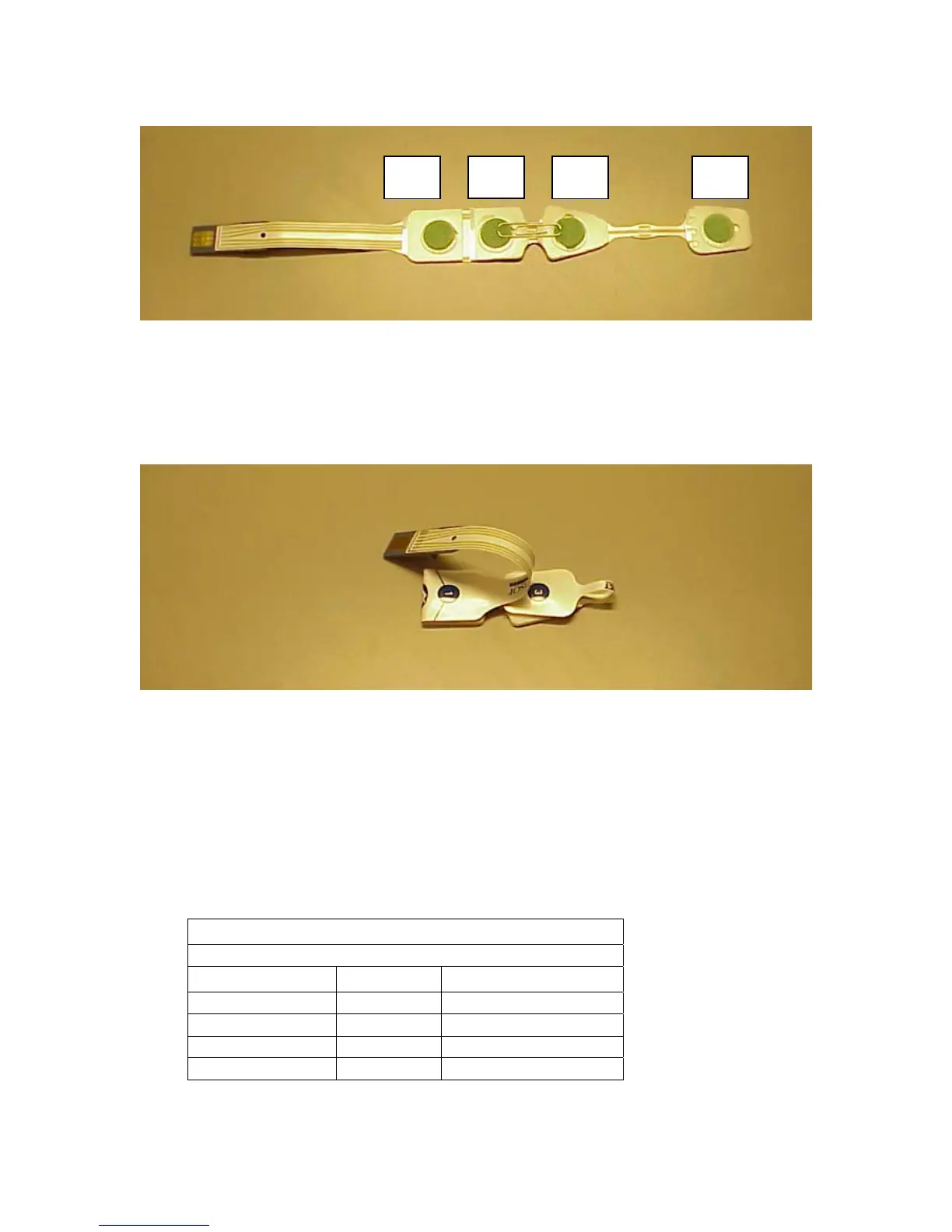
3. Fold electrode #3 over onto electrode #4, pressing adhesive surfaces together and
making sure the paper clip remains in place.
4. Fold electrode #1 over onto electrode #2.
Figure 12 - Connecting electrode #3 with #4, and #1 with #2.
5. Connect this Test Sensor to the PIC. All impedance tests should complete
successfully, with low impedance values. Typical values using this alternative Test
Sensor are less than 5 K ohms.
The following chart shows expected Test Sensor values:
Test Sensor Values
Electrode # Typical Range
1 1 K ohm 1-2 K ohms
2 1 K ohm 1-3 K ohms
4 1 K ohm 1-2 K ohms
3 1 K ohm 1-2 K ohms
#1 #2 #4 #3