EasyManua.ls Logo

Aspen ABM Series - User Manual

Aspen ABM Series
12 pages
Print Icon
To Next Page IconTo Next Page
Loading...
IO-123075 Effective 12-01-11
INSTALLATION & OPERATING INSTRUCTIONS
ABM SERIES MULTI-POSITION AIR HANDLER
(HYDRONIC HEAT)
These instructions should be retained and kept adjacent to the unit for future use
MODEL
(INCLUDING HEATER MODEL #) ________________________________
SERIAL #____________________________________________________
INSTALLER __________________________________________________
INSTALLATION DATE _________________________________________
Question and Answer IconNeed help?

Do you have a question about the Aspen ABM Series and is the answer not in the manual?

Summary

Safety Instructions

Hazard Warning Symbols

Explains symbols for hazard intensity and potential outcomes.

Qualification for Use

Specifies that certified technicians or NATE qualified individuals should use this information.

Power Disconnection Safety

Emphasizes disconnecting all power sources before servicing to prevent injury.

Code Compliance and Installer Responsibility

Highlights installer's duty to comply with local/national codes for safe installation.

Ventilation for Enclosed Areas

Stresses proper ventilation in enclosed spaces to prevent carbon monoxide hazards.

Authorized Kits and Accessories

Advises using only factory authorized kits and accessories for installation or modification.

Outdoor Installation Prohibition

States the unit is not approved for outdoor installations.

Electrical Power Requirements

Specifies the unit's design for 108/120 V, single-phase, 60 Hz power supply.

Product Inspection and Verification

Guides on visually inspecting for shipping damage and verifying product labels upon receipt.

Installation Preparation Guidelines

Instructs to read all guidelines carefully, clarify uncertainties, and gather tools before installation.

Clearance and Barrier Requirements

Details required clearances for service and protective barriers in certain areas.

Condensate Drain Installation

Outlines requirements for drain line pitch and condensate trap installation for proper drainage.

Ductwork Installation

Ductwork Standards Compliance

Mandates installation according to NFPA 90A/90B and NECA Manual K standards.

Vibration Isolation with Flexible Collars

Recommends using non-flammable flexible collars to prevent vibration transmission.

Air Drop Sizing and Ductwork Design

Advises on proper sizing of supply/return air drops and ductwork design for quiet operation.

Duct Insulation for Efficiency

Recommends insulating ductwork in unconditioned areas to prevent heat loss/gain.

General Installation Procedures

Unit Sizing Verification

Caution to ensure the unit is adequately sized and not to exceed outdoor unit tonnage.

Coil Preparation and Handling

Instructions on releasing nitrogen pre-charge and cleaning coil fins before installation.

Connection and Brazing Precautions

Details on preparing connection joints, avoiding damage, and brazing safety.

Hydronic Coil Water Connection Safety

Warning about connecting hot water supply and potential burn hazards.

Soldering Material Requirements

Specifies the use of only lead-free solder for water coil connections.

Schrader Valve Protection

Advises protecting Schrader valves and cores from heat during installation.

Metering Device Selection

Flowrator Coil Installation

Introduces flowrator coils and their installation requirements.

Piston Sizing for Flowrators

Emphasizes correct piston sizing for system performance and compressor protection.

Flowrator Piston Adjustment

Flowrator Piston Size Chart

Provides a table correlating outdoor unit capacity with required piston orifice sizes for R22 and R410A.

Flowrator Piston Change Procedure

Step-by-step instructions for disassembling, replacing, and reassembling the flowrator piston.

Teflon O-ring Installation

Highlights the critical importance of correctly seating the Teflon O-ring for a proper seal.

Piston Orientation Importance

Stresses the correct orientation of the piston into the distributor body to prevent operational damage.

TXV Coil Installation

TXV Brazing Protection

Warning to protect the TXV sensing bulb and body from overheating during brazing.

TXV Refrigerant Compatibility

Advises ensuring the selected TXV is compatible with the system's refrigerant (R22 or R410A).

TXV Valve Sizing

Recommends sizing TXV valves according to outdoor unit capacity to ensure performance.

TXV Bulb Mounting Guidelines

TXV Bulb Contact and Placement

Details the requirement for direct contact with the suction line and optimal positioning.

TXV Bulb Mounting Details

TXV Sensing Bulb Mounting Criteria

Lists the criteria for correct TXV sensing bulb mounting for accurate superheat control.

Vertical TXV Bulb Mounting

Provides instructions for mounting the TXV bulb vertically when horizontal mounting is not feasible.

Field Installed TXV Coils

TXV Installation Procedure

Step-by-step guide for installing a field-supplied expansion valve coil.

Brazing Safety for TXV Installation

Warning against touching hot braze joints during TXV installation to prevent burns.

TXV Installation without Schrader Ports

Specific instructions for installing TXV equalization tubes when Schrader ports are absent.

Hole Drilling Caution

Warning not to drill holes for chips that could enter the suction manifold.

TXV Assembly and Operation

TXV Assembly Components

Illustrates the components of a typical TXV assembly for reference.

Non-Bleed Expansion Valve Use

Notes that non-bleed expansion valves may require a hard-start kit.

Air Handler Installation Orientations

Permitted Installation Orientations

States the unit can be installed vertically or horizontally without modification.

Horizontal Installation Drain Pan Requirement

Mandates an auxiliary drain pan for horizontal installations to maintain warranty.

Horizontal Left Discharge Installation

Horizontal Left Installation Steps

Detailed steps for configuring the unit for horizontal left-hand airflow discharge.

Counter Flow Installation

Counter Flow Configuration Steps

Procedures for reconfiguring the air handler for counter flow operation.

Counter Flow Plate Placement

Instructions on positioning specific plates for the counter flow configuration.

Electrical Installation Guide

Electrical Installation Requirements

Outlines electrical supply, wiring, and code compliance for installation.

Micro-processor Control Board Overview

Describes the function of the control board and factory jumper settings.

Aquastat Jumper Configuration

Explains the setting of the aquastat jumper for blower operation.

Typical Electrical Connections

Provides typical electrical connection diagrams for A/C and heat pump applications.

Electrical Connections and Operation

Boiler and Valve Wiring

Details wiring connections for boiler terminals and external valves or pumps.

Hydronic Circulation and Blower Timing

Explains the sequence and timing for hydronic circulation and blower activation during heating.

Freeze Protection Sensor Function

Describes the freeze protection sensor and its role in preventing coil freezing.

Startup Procedures

Hydronic System Air Purging Warning

Emphasizes purging air from the hydronic coil and lines before starting the pump.

Hot Water Temperature Requirements

Specifies the safe operating range for hot water supply to the coil and burn hazard warnings.

Hydronic System Connection Details

Guides on connecting the hydronic coil to the water heater system using flexible piping.

System Purging Process

Step-by-Step System Purging

Detailed instructions for purging air from the hydronic system and coil.

System Startup and Calibration

Water Heater Thermostat Adjustment

Instructs on adjusting the water heater thermostat for optimal coil temperature.

Heat Anticipator Adjustment

Guides on adjusting the heat anticipator for proper cycle length and unit operation.

Performance Testing and Calibration

Electric Heat Control Settings

Details thermostat settings and system switch positions for electric heat operation.

Airflow Adjustment Procedures

Explains how to adjust dampers, registers, and motor speed for required airflow.

Airflow Verification Methods

Describes methods for checking airflow, including temperature rise and CFM calculation.

CFM Calculation Formula

Provides the formula for calculating CFM based on BTUH output and temperature rise.

Operation and Maintenance Overview

Key Component Descriptions

Offers brief descriptions of the unit's key components and installation concepts.

General Operation and Maintenance

Room Thermostat Function and Placement

Explains the room thermostat's role, optimal placement, and maintenance.

Air Filter Function and Maintenance

Details the importance of air filters for system cleanliness and efficiency, and their maintenance.

Electrical Protection (Fuses;Breakers)

Stresses the importance of circuit breakers for over-current protection and identifying them.

Critical Safety Warnings

Lists crucial safety warnings including storage of flammables, panel removal, and identifying shut-off devices.

Periodic Checkup and Service Importance

Highlights the necessity of annual checkups and cleaning for performance and longevity.

Motor Lubrication

Notes that direct drive blower motors have permanently lubricated bearings and require no further lubrication.

Air Filter Replacement Guidelines

Advises on replacing air filters with the same type and size as originally furnished.

ABM Hydronic Related Information

Equipment Sizing Considerations

Guides on selecting an air handler with adequate heating output and matching cooling coil size.

Water Heater Sizing Factors

Provides guidance on selecting appropriate water heater gallon capacity and BTU input.

Water Heater Capacity Guide

Lists minimum water heater gallon capacities based on system CFM requirements.

Water Heater BTU Input Calculation

Offers a method to calculate required water heater BTU input based on structure's heat loss.

Pump Replacement Procedure

Outlines preliminary steps before servicing or replacing the pump.

Pump Replacement and Maintenance

Pump Replacement Steps

Detailed steps for removing, replacing, and re-installing the pump housing assembly.

Common Problems and Solutions

Noisy Pump Troubleshooting

Suggests purging the system again if a noisy pump is encountered.

T&P Valve Issues

Addresses potential causes for T&P valve weeping, such as backflow preventers or expansion tanks.

Hot Water Circulation During Cooling

Identifies a stuck check valve as a cause for hot water circulation during cooling cycles.

Little or No Heat Troubleshooting

Lists potential causes for lack of heat, including system purging, reversed connections, and undersized components.

Wiring Diagrams and Electrical Details

Low Voltage Thermostat Wiring

Details the wiring connections for the low-voltage thermostat to the unit.

High Voltage Power Supply Wiring

Illustrates the high-voltage power supply connections and warnings.

Wiring Diagram Notes and Color Codes

Explains important notes, wire color codes, and diagram numbering for electrical connections.

Overview

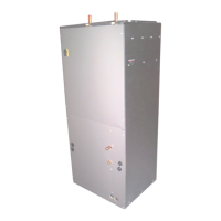
This document provides installation and operating instructions for the ABM Series Multi-Position Air Handler with Hydronic Heat. It covers various aspects of the unit, including safety, installation procedures, electrical connections, and maintenance.

Function Description

The ABM Series Multi-Position Air Handler is designed to provide heating and cooling for residential and commercial spaces. It is a versatile unit that can be installed in multiple positions, including horizontal left discharge, horizontal right discharge, upflow, and counterflow, to suit different installation requirements. The unit incorporates hydronic heat, meaning it uses hot water circulating through coils to provide heating. This system is designed to work in conjunction with an outdoor condensing unit for cooling and a boiler or water heater for heating.

The air handler's primary function is to circulate conditioned air throughout a building. During the heating cycle, hot water from an external source (boiler or water heater) flows through the hydronic coil, transferring heat to the air. A blower motor then distributes this warmed air through the ductwork. In the cooling cycle, the unit works with an outdoor condensing unit, where refrigerant flows through an evaporator coil within the air handler, absorbing heat from the indoor air. The blower then circulates the cooled air.

A key component of the system is the expansion valve, which regulates the flow of refrigerant into the evaporator coil, optimizing cooling performance. For hydronic heating, the unit includes a micro-processor based control board that manages the electrical functions, including the blower motor and pump (if installed). The system is designed to be controlled by a remote thermostat, allowing users to set desired temperatures for both heating and cooling.

Usage Features

The ABM Series Air Handler offers several features that enhance its usability and adaptability. Its multi-position design allows for flexible installation in various orientations, which is crucial for fitting into different building layouts and existing ductwork configurations. The unit can be configured for upflow, downflow (counterflow), horizontal left, or horizontal right discharge, making it suitable for a wide range of applications.

For heating, the unit utilizes hydronic coils, which can be connected to a boiler or a water heater. The control board includes settings for managing the hydronic heat, such as an aquastat jumper that can be set to "ON" if an aquastat is used, ensuring the blower is energized at appropriate temperatures. If a pump is factory-installed, it will be energized automatically on a call for heat. For units without a factory-installed pump, two black wires need to be connected to the boiler terminals.

The unit's blower motor offers multiple speeds (high, medium, low) to adjust airflow based on heating or cooling demands and external static pressure. This allows for fine-tuning of air delivery to achieve optimal comfort and efficiency. The installation instructions provide a table of CFM (Cubic Feet per Minute) values at various external static pressures for different models and motor speeds, aiding installers in setting up the system correctly.

The air handler is designed to be controlled by a 24V remote thermostat, which typically offers settings for fan operation (on/auto) and system mode (heat/cool). The electrical connections are straightforward, with clear diagrams provided for connecting the thermostat, condensing unit, and boiler/zone valve.

The unit also features a freeze protection sensor, which is a safety mechanism to prevent damage from freezing temperatures, particularly important for the hydronic components.

Maintenance Features

Regular maintenance is crucial for the longevity and efficient operation of the ABM Series Air Handler. The manual emphasizes several key maintenance aspects:

  • Filter Replacement: Air filters should be cleaned or replaced regularly (monthly is recommended) to maintain good indoor air quality and prevent airflow restrictions. Dirty filters can reduce efficiency and cause the unit to work harder, leading to increased energy consumption and potential damage. Access panels are designed to facilitate easy filter removal and replacement.
  • Coil Cleaning: The evaporator and hydronic coils should be inspected periodically for dirt and debris accumulation. While the manual doesn't detail coil cleaning procedures, it implies that clean coils are essential for optimal heat transfer and efficiency.
  • Drain Pan Maintenance: The condensate drain pan and line should be checked regularly for blockages and cleaned to prevent overflow and potential water damage. The manual provides instructions for installing a proper drain trap to ensure effective condensate removal.
  • Blower Motor and Fan: The blower motor and fan assembly should be inspected for cleanliness and proper operation. Lubrication of the blower motor is generally not required as it uses permanently lubricated bearings.
  • Electrical Connections: All electrical connections should be checked periodically for tightness and signs of corrosion. This includes connections to the power supply, thermostat, and any external components like the boiler or condensing unit.
  • Expansion Valve/Flowrator Maintenance: For units with a flowrator, the piston may need to be changed to match the outdoor unit's capacity. The manual provides detailed instructions on how to disassemble the flowrator body, replace the piston, and reassemble it, emphasizing the importance of correct piston orientation and proper sealing with the Teflon O-ring. For TXV (Thermostatic Expansion Valve) coils, instructions are given for installing the TXV, including proper bulb mounting and brazing techniques.
  • Hydronic System Maintenance: For hydronic heat systems, regular purging of air from the system is necessary to prevent noisy pump operation and ensure proper heat circulation. The manual outlines a detailed procedure for purging the system, including opening air bleed valves and circulating water. The water heater thermostat setting should be adjusted to ensure the hot water coils receive water at the appropriate temperature (120-180°F).
  • Troubleshooting: The manual includes a section on common problems and solutions, such as noisy pump operation, T&P valve weeping, hot water circulation during cooling, and insufficient heat from the water coil. These sections guide users and technicians in diagnosing and resolving common issues.
  • Professional Servicing: The document recommends that certain tasks, especially those involving electrical work or refrigerant handling, be performed by qualified service technicians. This ensures safety and proper functioning of the unit.

By following these maintenance guidelines, users can ensure the ABM Series Air Handler operates efficiently, reliably, and safely for many years.

Aspen ABM Series Specifications

General IconGeneral
TypeModular Air Handler
Airflow Range6, 000 to 60, 000 CFM
Voltage Options208/230V, 460V, 575V
ConstructionGalvanized steel
Filterspleated
Coil Optionshot water, steam
ControlsFactory-mounted

Related product manuals