37
Caution
1. Without SATA 15-pin power connector interface, the SATA3 Hot Plug cannot be
processed.
2. Even some SATA3 HDDs provide both SATA 15-pin power connector and IDE
1x4-pin conventional power connector interfaces, the IDE 1x4-pin conventional
power connector interface is de nitely not able to support Hot Plug and will cause
the HDD damage and data loss.
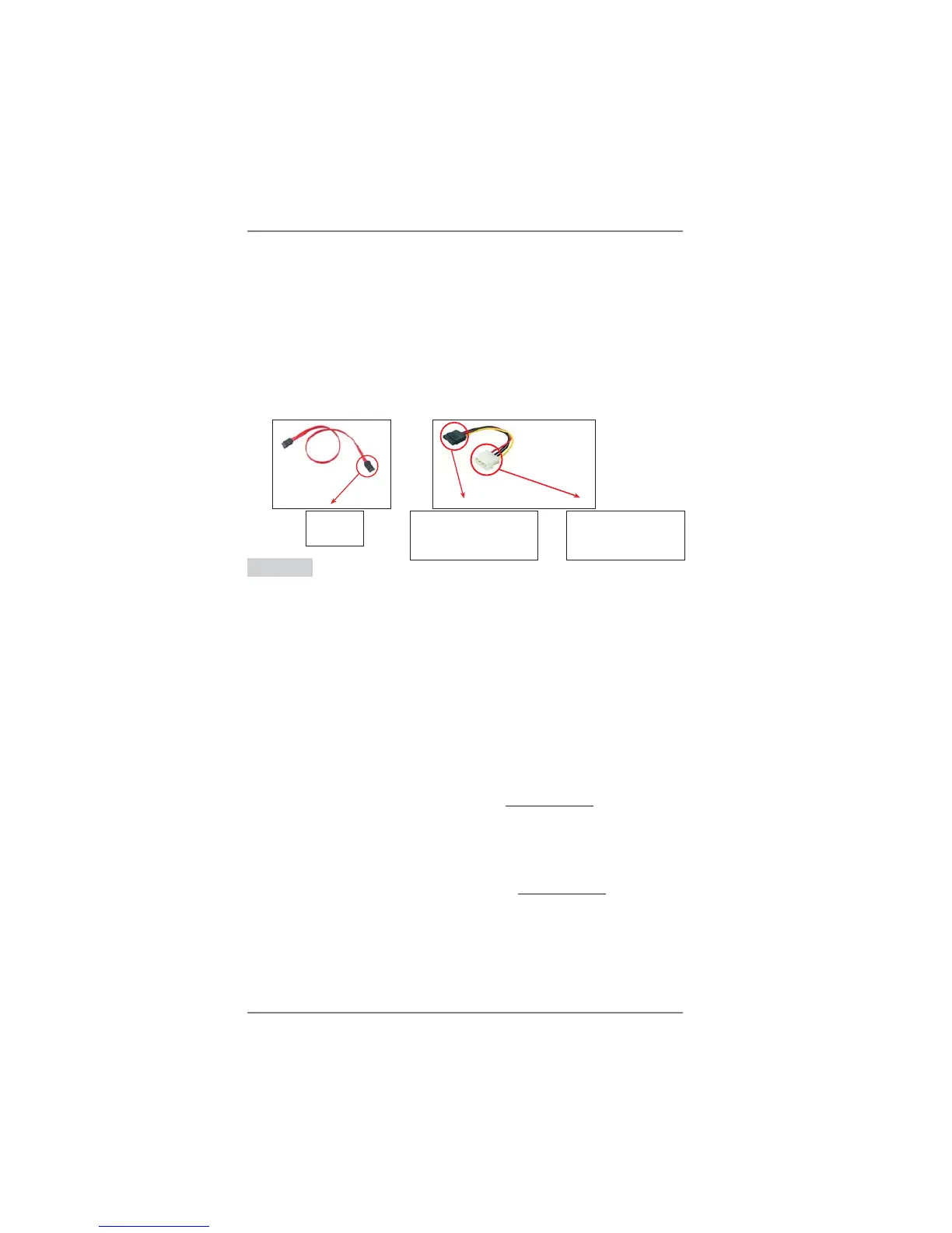
SATA 7-pin
connector
A. SATA data cable (Red) B. SATA power cable
2.13 SATA3 HDD Hot Plug Feature and Operation Guide
This motherboard supports Hot Plug feature for SATA3 HDD in RAID / AHCI
mode. Please read below operation guide of Hot Plug feature carefully. Before you
process the SATA3 HDD Hot Plug, please check below cable accessories from the
motherboard gift box pack.
A. 7-pin SATA data cable
B. SATA power cable with SATA 15-pin power connector interface
The SATA 15-pin power
connector (Black) connect
to SATA3 HDD
Points of attention, before you process the Hot Plug:
1. Below operation procedure is designed only for our motherboard, which supports
SATA3 HDD Hot Plug.
* The SATA3 Hot Plug feature might not be supported by the chipset because of
its limitation, the SATA3 Hot Plug support information of our motherboard is
indicated in the product spec on our website: www.asrock.com
2. Make sure your SATA3 HDD can support Hot Plug function from your dealer or
HDD user manual. The SATA3 HDD, which cannot support Hot Plug function, will
be damaged under the Hot Plug operation.
3. Please make sure the SATA3 driver is installed into system properly. The latest
SATA3 driver is available on our support website: www.asrock.com
4. Make sure to use the SATA power cable & data cable, which are from our
motherboard package.
5. Please follow below instructions step by step to reduce the risk of HDD crash or
data loss.
1x4-pin conventional
power connector (White)
connect to power supply