18
2.4 Installation of CPU Fan and Heatsink
This motherboard is equipped with 1155-Pin socket that supports Intel 1155-Pin
CPUs. Please adopt the type of heatsink and cooling fan compliant with Intel 1155-
Pin CPU to dissipate heat. Before you install the heatsink, you need to spray ther-
mal interface material between the CPU and the heatsink to improve heat dissipa-
tion. Ensure that the CPU and the heatsink are securely fastened and in good con-
tact with each other. Then connect the CPU fan to the CPU_FAN connector (CPU_
FAN1, see page 13, No. 4).
For proper installation, please kindly refer to the instruction manuals of your
CPU fan and heatsink.
Below is an example to illustrate the installation of the heatsink for 1155-Pin CPUs.
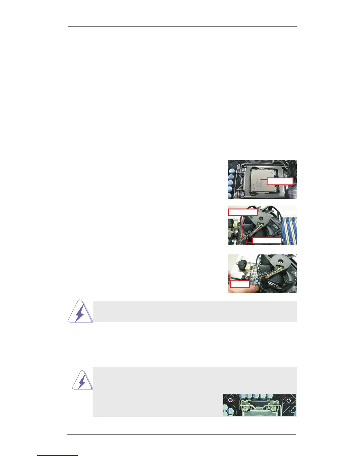
Step 1. Apply thermal interface material onto the cen-
ter of the IHS on the socket’s surface.
Step 2. Place the heatsink onto the socket. Ensure
that the fan cables are oriented on side closest
to the CPU fan connector on the motherboard
(CPU_FAN1, see page 13, No. 4).
Step 3. Align fasteners with the motherboard through-
holes.
Step 4. Rotate the fastener clockwise, then press
down on fastener caps with thumb to install
and lock. Repeat with remaining fasteners.
If you press down the fasteners without rotating them clockwise, the
heatsink cannot be secured on the motherboard.
Step 5. Connect fan header with the CPU fan connector on the motherboard.
Step 6. Secure redundant cable with tie-wrap to ensure the cable does not
interfere with fan operation or contact other components.
Please be noticed that this motherboard supports Combo Cooler
Option (C.C.O.), which provides exible options to adopt three dif-
ferent CPU cooler types, Socket LGA 775, LGA 1155 and LGA 1156.
The white throughholes are for Socket LGA
1155/1156 CPU fan.
 Loading...