22 23
English
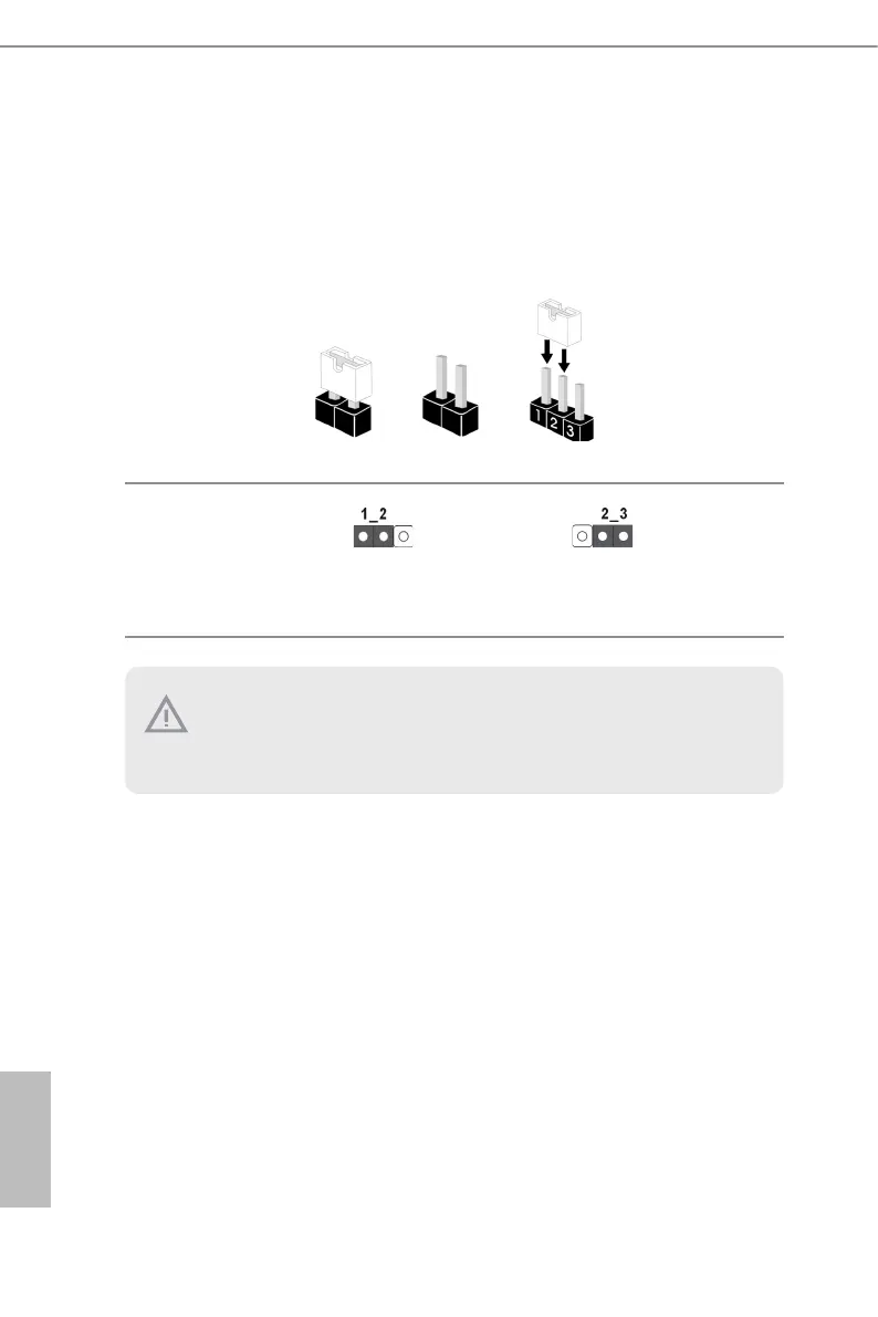
2.6 Jumper Setup
e illustration shows how jumpers are setup. When the jumper cap is placed on the pins,
the jumper is “Short”. If no jumper cap is placed on the pins, the jumper is “Open”. e
illustration shows a 3-pin jumper whose pin1 and pin2 are “Short” when a jumper cap is
placed on these 2 pins.
PCIE Signal Source Selec-
tion Jumper
(3-pin PCIE7_MCIO2_SW)
(see p.6, No. 36)
PCIE7(x4) + MCIO2(x4)
PCIE7(x8) (Default)
1. SLOT7 shares lanes with MCIO1 and MCIO2. MCIO1 and MCIO2 will be disabled
when SLOT7 is populated.
2. SLOT1 shares lanes with MCIO4 and M2_2. SLOT1 auto-switch to PCIe5.0 x8
when MCIO4 and M2_2 are populated.
 Loading...